TL;DR
I am trying to record the speed and position of a rotating shaft in time. Unfortunately, I have issues with getting expected measurements when using the CHANGE interrupt.
I am trying to record the movement of a rotating shaft. More specifically the time it takes for the shaft to move from one position to the next and the location of the shaft at those moments. I need this data to control external equipment that depends on the location of the shaft and the change in speed from previous to the current position. The shaft rotates at around 1-2 times per second. Rotation is only in one direction.
Unfortunately, I have issues with getting expected measurements when using the CHANGE interrupt. More specifically when I use the code below to record the time between the slits, the values show that every second measurement is roughly twice as long as the one before it.
For example: 10064-5408-10160-5444.
If I replace the CHANGE interrupt to RISING, then the doubling of the values goes away and the results are as expected. I know I could just redesign the multi-slit encoder to have enough slits for my applications while using the RISING interrupt instead of the CHANGE, but I want to understand why this happens, so I could use the CHANGE if I need even more resolution.
Info about the encoder discs
The encoder discs are 3D printed with PETG and are made so all slits are identical and evenly spread. (See attached photo) The individual slits are 4mm wide to give the Photo Interrupter the best chance of recording the slit. The multi-slit encoder has 15 slits, this means with the CHANGE interrupt I get 30 measurements and with the RISING/FALLING I get 15. I am not missing any slit counts, as seen from the provided data.
Encoder with only one slit keeps track of full rotations and gives me a reference point for the location. The multi-slit encoder is used to provide the individual positions during the rotation. The time between the positions is calculated based on the times that I record when the Photo Interrupter output changes.
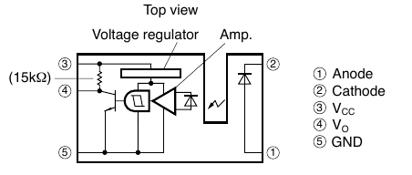
To detect the slits I am using the Photo Interrupter - GP1A57HRJ00F, that is soldered to a breakout board.
The breakout board outputs are connected to the Arduino interrupt pins 2 and 3.
The code (See at the end of the post) is made only to test this issue and is as barebones as I could make it. It keeps track of the shaft rotation and notes the time when a slit is detected by the interrupt routine. The gap between is calculated outside of the code by use of LibreOffice Calc, to remove any programming issues that I might have. The gap is calculated like this:
Latest time - Previous time = Gap
I have added the Calc file (Unable to upload this file, saved it as PDF now) that has the data collected from the serial monitor in both the RISING and CHANGE interrupts. The measurements are done by rotating the shaft by hand and letting it come to a stop on its own.
Also added is a photo of the encoder disks and their placement.
I hope someone can help me understand what is going on and if this is due to my design or something else.
// Pin allocations
#define interruptPinS 3     //Single slit encoder pin
#define interruptPinM 2     //Multi slit encoder pin

// Variables inside interrupts can be changed at any moment. needs to be volatile
volatile unsigned long endTime;
volatile int slitcount = 0;            //counter for seeing how many slits have passed since the zeroing

void setup() {
  Serial.begin(115200);
  //Pin Setup
  pinMode(interruptPinS, INPUT_PULLUP);
  pinMode(interruptPinM, INPUT_PULLUP);
  attachInterrupt(digitalPinToInterrupt (interruptPinS), ChangeSingle, RISING);    // attach interrupt handler RISING
  attachInterrupt(digitalPinToInterrupt (interruptPinM), ChangeMulti, CHANGE);     // attach interrupt handler CHANGE or RISING
  endTime = micros ();
}

void ChangeSingle() {        //interrupt section that checks if the single slit encoder has passed
  slitcount = 0;             // zeroes the slitcount after one full rotation
}

void ChangeMulti() {                  //interrupt section that checks if the multi slit encoder has passed
  endTime = micros ();              //Recording the time when the interrupt happened.
  slitcount++;                      //add one to slitcount
  }

void loop (){
  if (endTime)                    //If there was a new recorded time in he ChangeMulti()
  {
    Serial.print (endTime);       //Print the value of the recorded time of multislit passing
    Serial.print (", ");
    Serial.println (slitcount);   //Print the value of the slits that have passed
    endTime = 0;                  //Zeroes the endTime so the loop will only activate when theres new data
  }
}  // end of loop


20-05-17 - Measurement data.pdf (24.7 KB)