Because it is a non-issue from Imaginaryland.
My Uno cpu runs at 16 million cycles per second no matter what it does. What uses more power than that are OUTPUT mode sourcing and sinking of current to run things.
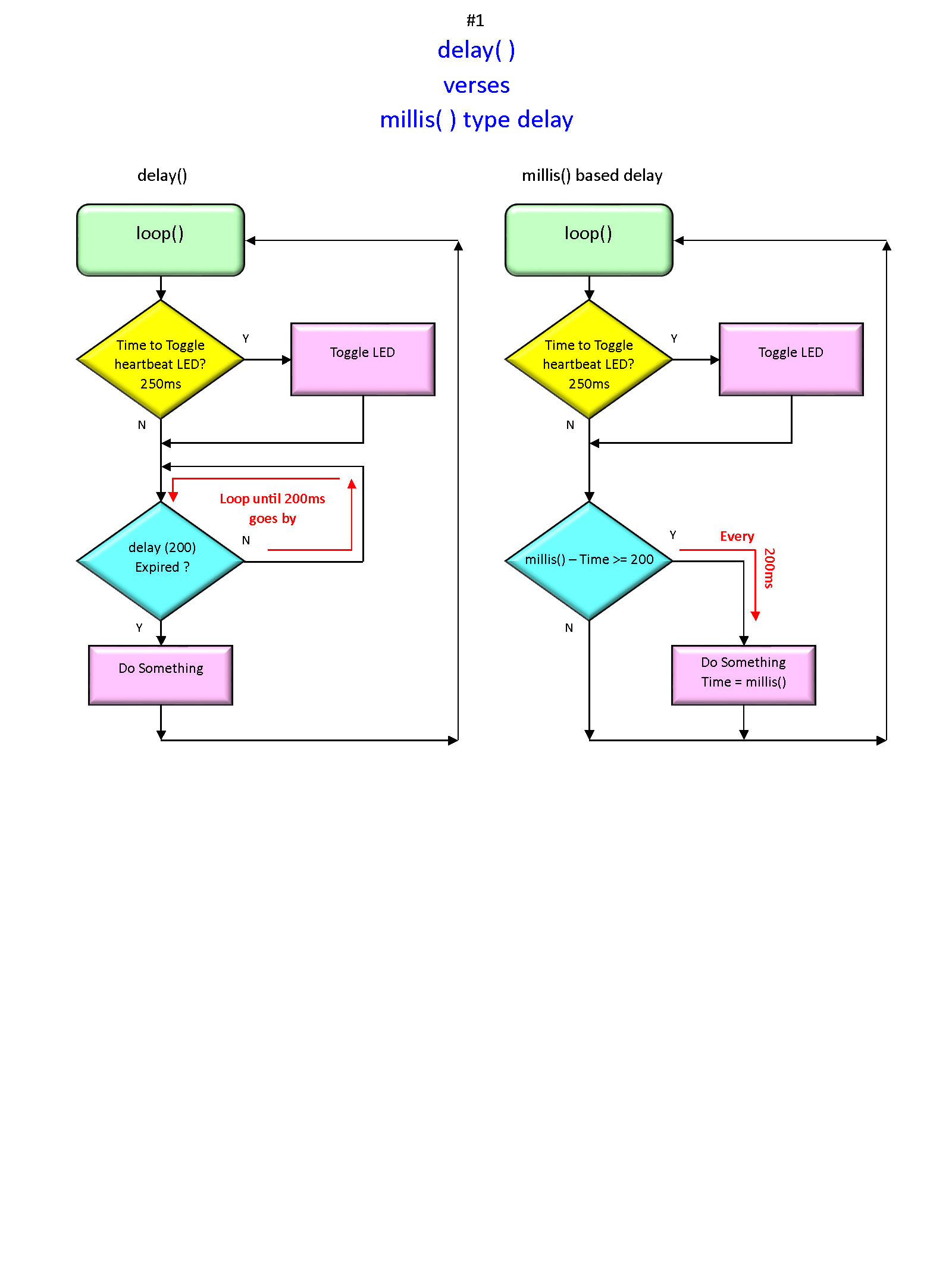
What delay does is watch a timer with total code fixation, Nothing Else Runs Until It Is Finished. There are quite a few commands that force a wait... and during that wait every cycle is wasted.
example uses a led that you don't have to wire since Serial Monitor gets the log. Just run it, it stops itself.
/*
  DelayBlink for expierienced users of delay().
  Turns on an LED on for one second, then off for one second, repeatedly.
  Added to tha, blink another led for a short time repeatedly and
  gemerate a time-stamped log of LED actions, hit Enter to stop/start.
  With the log there is no real need to wire in the extra LED.

  This example code is in the public domain.
 */

// Pin 13 has an LED connected on most Arduino boards.
// give it a name:
byte led = 13;
byte led2 = 7;

byte loops = 0;
byte limitLoopsTo = 5; // stop scrolling forever

// the setup routine runs once when you press reset:
void setup()
{
  Serial.begin( 115200 );  // Serial Monitor must match.
  Serial.println( F( "\n\n**** DelayBlink demo. ****" )); // '\n' is newline char
  Serial.println( F( "Log times are milliseconds since start." ));
  Serial.println( F( "~~~~~~~~~~~~~~~~~~~~~~~~~~~~~\n" ));


  // initialize the digital pins as outputs.
  pinMode(led, OUTPUT);
  pinMode(led2, OUTPUT); // if phase 2 is used
}

// the loop routine runs over and over again forever:
void loop()
{
  loops++; // loop count

  digitalWrite(led, HIGH);   // turn the LED on (HIGH is the voltage level)
  Serial.print( millis());
  Serial.println( F( " LED 13 ON" ));
  delay(1000);               // wait for a second
  digitalWrite(led, LOW);    // turn the LED off by making the voltage LOW
  Serial.print( millis());
  Serial.println( F( " LED 13 OFF" ));
  delay(1000);               // wait for a second

//  you have 2 leds on different pins
  digitalWrite(led2, HIGH);   // turn the LED on (HIGH is the voltage level)
  Serial.print( millis());
  Serial.println( F( " LED 7 ON" ));
  delay(200);               // wait for 0.2 second
  digitalWrite(led2, LOW);    // turn the LED off by making the voltage LOW
  Serial.print( millis());
  Serial.println( F( " LED 7 OFF" ));
  delay(200);               // wait for 0.2 second
//  what happens?
  if ( loops == limitLoopsTo )
  {
    while( 1 ); // always true, locked loop can be reset
  }
}
Cut&Paste the log works but just note how the short blink only follows a long one.
Execution with delay is serial.
Execution without delay is parallel.
/*
  Modified Arduino Blink Converted to NoDelayBlink
  Blinks two leds at different rates at the same time.
  This is for after you have practice with delay code.

  You may have to see it run to know what the deal is,
  but just in case,
  it means merged sketched can run independently
  if one thing runs with delays alone it can be made to run withs others.
  And if no task hogs cycles an Uno can do > 100 tasks without stuttering.

  This example code is in the public domain.
 */

// stop the log at millis to linit length
const unsigned long demoLength = 12000;

// Pin 13 has an LED connected on most Arduino boards.
// give it a name:
byte statusLedPin = 13; // save a byte, Uno has 2048B RAM!
byte statusLedState = 1; // turns ON in setup
byte addedLedPin = 7; // phase 3
byte addedLedState = 1; // turns ON in setup

unsigned long statusLedStart; // gets set at start
unsigned long addedLedStart; // millis!

unsigned long statusLedInterval = 1000; // millis!
unsigned long addedLedInterval = 200; // millis!

void BlinkStatusLight() // shows normal operation
{
  if ( millis() - statusLedStart >= statusLedInterval )
  {
    statusLedState = !statusLedState; // flips 0/1
    digitalWrite(statusLedPin, statusLedState); // turn the LED on (HIGH is the voltage level)
    statusLedStart += statusLedInterval; // self-correcting

    Serial.print( millis());
    Serial.print( F( " LED " ));
    Serial.print( statusLedPin );
    Serial.write( ' ' );
    if ( statusLedState == 0 )
    {
      Serial.println( F( "OFF" ));
    }
    else
    {
      Serial.println( F( "ON" ));
    }
  }
} // end of BlinkStatusLight(), it toggles a pin on time

// blinking the added led is really the same as above.
// pnly 1 task can do both BUT
// blinking a led is a filler for Output in general
// this demo is to show independent tasks running.
void BlinkAddedLed() // shows normal operation
{
  if ( millis() - addedLedStart >= addedLedInterval )
  {
    addedLedState = !addedLedState; // flips 0/1
    digitalWrite(addedLedPin, addedLedState); // turn the LED on (HIGH is the voltage level)
    addedLedStart += addedLedInterval; // self-correcting

    Serial.print( millis());
    Serial.print( F( " LED " ));
    Serial.print( addedLedPin );
    Serial.write( ' ' );
    if ( addedLedState == 0 )
    {
      Serial.println( F( "OFF" ));
    }
    else
    {
      Serial.println( F( "ON" ));
    }
  }
} // end of BlinkAddedStatusStatusLight(), it toggles a pin on time


// One more task that measures the void loop average.
// First time was a shock, loop averaged 20 micros.
// It made 67 time checks per timer before 1 ms.
// LoopCounter  --  lets you know how often void loop() ran last second.
// LoopCounter value
#define microsInOneSecond 1000000UL


void LoopCounter() // tells the void loop runs every second
{ // if you add code, this will show you the load
  // it is a load, converting longs to decimal text
  // takes a lot of cycles but only once/second.

  // When you are finished with developing,
  // comment out the void loop call to the counter
  // and your finished code will have less ;atency.

  // inside a function, static variables keep their value from run to run
  static unsigned long count, countStartMicros; // only this function sees these

  count++; // adds 1 to count after any use in an expression, here it just adds 1.
  if ( micros() - countStartMicros >= microsInOneSecond ) // 1 second
  {
    countStartMicros += microsInOneSecond; // for a regular second
    Serial.print( F( "\nLC " ));
    Serial.println( count ); // 32-bit binary into decimal text = many micros
    count = 0; // don't forget to reset the counter
  }
} // end of LoopCounter(), it shows void loop runs every second.


//  ============= VOID SETUP ==============
void setup()
{ // easier for old eyes to match aligned braces

  Serial.begin( 115200 ); // empty the buffer faster!
  // set your Serial Monitor baud rate to match!
  Serial.println( F( "\n\n**** NoDelayBlink demo. ****" ));
  Serial.println( F( "Log times are milliseconds since startup." ));
  Serial.println( F( "Demo limited to 12 seconds originally." ));
  Serial.println( F( "~~~~~~~~~~~~~~~~~~~~~~~~~~~~~\n" ));

  // initialize the digital pin as an output.
  pinMode(statusLedPin, OUTPUT);
  pinMode(addedLedPin, OUTPUT);

  // leds ON, waiting to turn OFF unless I want else.
  digitalWrite(statusLedPin, HIGH); // turn the LED on (HIGH is the voltage level)
  digitalWrite(addedLedPin, HIGH); // turn the LED on (HIGH is the voltage level)
} // the vertically alighned closing brace


//  ============= VOID LOOP ==============
void loop()  // the driving wheel
{
  // these tasks will appear to run in parallel
  LoopCounter();
  BlinkStatusLight();
  BlinkAddedLed();
  // every time loop runs they all check the time

  if ( millis() >= demoLength )
  {
    while( 1 ); // no escape
  }
}
This is how you can write tasks that run independent of each other.
I watch a button with one task that maintains 8 bits of pin state history that other tasks can read to know when a state change and debounce just happened by if ( history == 128 ) { code for button press }.
It's tight which runs in fewer cycles, less electricity.
Writing separate tasks reduces your indent levels, makes the logic easier to follow and debug. You can work with a task in one simple sketch in order to include it in a larger sketch and save in your own task toolbox.
Non-blocking code is VERY mix and match.