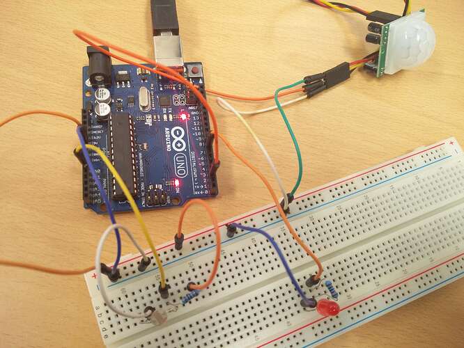
Doorhandle Light - Photo Resistor Triggers PIR Sensor Triggers LEDs - NEED HELP

Hello,

I am currently working on a school project: a device that sits adjacent to a door handle and lights up during nighttime when a person is detected moving in front of it. The device is to help seniors with bad eyesight or that are sensitive to light.

The device includes a photo resistor, that when the room goes below a certain level of darkness, turns on the motion sensor. This motion sensor then subsequently turns on LEDs that light up the door handle, when motion is detected in front of the device.

I have found a very similar project on the forums, but I have tried wiring everything up and uploading the code, yet still it does not work: Motion & Light Activated Night-light (lights up if it's dark & there is motion) - Project Guidance - Arduino Forum

This is the first time I am working with Arduino's, and I realize that this project may be rather complex, but it is important to me. I am working with an Arduino Uno, and I need help checking if my setup and my code is correct. Both are attached below. I have also included a flowchart, so that you get the idea of the function of the device.

/* 
* //////////////////////////////////////////////////
* //making sense of the Parallax PIR sensor's output
* //////////////////////////////////////////////////
*
* Switches a LED according to the state of the sensors output pin.
* Determines the beginning and end of continuous motion sequences.
*
* @author: Kristian Gohlke / krigoo (_) gmail (_) com / http://krx.at
* @date:   3. September 2006 
*
* kr1 (cleft) 2006 
* released under a creative commons "Attribution-NonCommercial-ShareAlike 2.0" license
* http://creativecommons.org/licenses/by-nc-sa/2.0/de/
*
*
* The Parallax PIR Sensor is an easy to use digital infrared motion sensor module. 
* (http://www.parallax.com/detail.asp?product_id=555-28027)
*
* The sensor's output pin goes to HIGH if motion is present.
* However, even if motion is present it goes to LOW from time to time, 
* which might give the impression no motion is present. 
* This program deals with this issue by ignoring LOW-phases shorter than a given time, 
* assuming continuous motion is present during these phases.
*  
*/

/////////////////////////////
//VARS
//the time we give the sensor to calibrate (10-60 secs according to the datasheet)
int calibrationTime = 20;        

//the time when the sensor outputs a low impulse
long unsigned int lowIn;         

//the amount of milliseconds the sensor has to be low 
//before we assume all motion has stopped
long unsigned int pause = 5000;  

boolean lockLow = true;
boolean takeLowTime;  

int pirPin = 2;    //the digital pin connected to the PIR sensor's output PIR Sensor (Rev B) 555-28027
int ledPin = 7;
int lightPin = 0;  //Photoresistor - VT935G-B  350-00009
int threshold = 120;

/////////////////////////////
//SETUP
void setup(){
  Serial.begin(9600);
  pinMode(pirPin, INPUT);
  pinMode(ledPin, OUTPUT);
  digitalWrite(pirPin, LOW);
  pinMode(lightPin, INPUT);
  //give the sensor some time to calibrate
  Serial.print("calibrating sensor ");
    for(int i = 0; i < calibrationTime; i++){
      Serial.print(".");
      delay(1000);
      }
    Serial.println(" done");
    Serial.println("SENSOR ACTIVE");
    Serial.println(analogRead(lightPin));
    delay(50);
  }

////////////////////////////
//LOOP
void loop(){


     if(digitalRead(pirPin) == HIGH && (analogRead(lightPin)) > threshold) {
       digitalWrite(ledPin, HIGH);   //the led visualizes the sensors output pin state
       if(lockLow){  
         //makes sure we wait for a transition to LOW before any further output is made:
         lockLow = false;            
         Serial.println("---");
         Serial.print("motion detected at ");
         Serial.print(millis()/1000);
         Serial.println(" sec"); 
         Serial.println(analogRead(lightPin)); 
         delay(50);
         }         
         takeLowTime = true;
       }

     if(digitalRead(pirPin) == LOW){       
       digitalWrite(ledPin, LOW);  //the led visualizes the sensors output pin state

       if(takeLowTime){
        lowIn = millis();          //save the time of the transition from high to LOW
        takeLowTime = false;       //make sure this is only done at the start of a LOW phase
        }
       //if the sensor is low for more than the given pause, 
       //we assume that no more motion is going to happen
       if(!lockLow && millis() - lowIn > pause){  
           //makes sure this block of code is only executed again after 
           //a new motion sequence has been detected
           lockLow = true;                        
           Serial.print("motion ended at ");      //output
           Serial.print((millis() - pause)/1000);
           Serial.println(" sec");
           Serial.println(analogRead(lightPin)); 
           delay(50);
           }
       }
  }

Please help me.

The flowchart doesn't correspond with either what you say you want to happen, or with the program. It deoperates with an ultrasonic ranging module, not with a PIR detector.

Also, the PIR detector shown in your photo isn't the Parallax one, so a lot of the code is unnecessary. The type that you show doesn't have the fault listed in the program's comments:-

However, even if motion is present it goes to LOW from time to time,
which might give the impression no motion is present.
This program deals with this issue by ignoring LOW-phases shorter than a given time,
assuming continuous motion is present during these phases.

I've used the type of detector that you have a couple of times, and never had the problem described above.
After triggering, the PIR output will go high for the period set by it's timer, then go low unless another trigger has occurred during that period. It's retriggerable, so if movement is detected within the time that the output is high, the time period is restarted.

So you can actually remove most of the code.

That's great! But does this mean that I cannot use the PIR sensor for this particular project? By that I mean, is it even possible for me to use the PIR sensor in combination with the photo resistor and the LEDs?

Also, is the code correct but simply needs for me to delete the parts particular to the Parallax sensor? If not, where can I find a piece of code that describes the actions described in my project i.e. photo resistor activates PIR sensor actives LEDs, and then loops?

16adamm:
That's great! But does this mean that I cannot use the PIR sensor for this particular project?

No, not at all. The PIR is fine. And that type works very well. I have two identical PIR detectors in my woodwork workshop, used as burglar alarm sensors

By that I mean, is it even possible for me to use the PIR sensor in combination with the photo resistor and the LEDs?

Yes, it's a good system.

Also, is the code correct but simply needs for me to delete the parts particular to the Parallax sensor? If not, where can I find a piece of code that describes the actions described in my project i.e. photo resistor activates PIR sensor actives LEDs, and then loops?

You need to write the code. If you search hard enough, you might find something similar that you can modify, but surely it's better that you learn to write your own code that does exactly what you want?

The calibration time will probably need to be increased from it's current value of 20 seconds, too. I found with my PIR detectors that they took 30 to 40 seconds to settle down on power up, during which time they false-triggered a couple of times. Do that in the 'setup()' function.

To write your program, draw yourself a flow-chart or pseudo-code, covering exactly how you want the program to function, then write code that follows the flow-chart / pseudo-code.

Basically, what I'd do is create a boolean variable called "isDark" or similar. Then at the start of the 'loop()' function, check the LDR value and if the light level is below your threshold, set "isDark" to true, otherwise set it to false.

Then, only check the PIR detector and light the LED(s) if "isDark" is true.

Fairly straightforward, and good programming practice. Have a shot at writing it, and if you run into problems, post your code here and we can help you get it working properly.
Good luck, and have fun......

Thanks a bunch! okay here is the pseudo-code I have written, please tell me if I'm on the right track:

  1. #include, #define, constants, etc.
    // pin assignments
    1.1. int ldrPin = 7 // chose the LDR input pin
    1.2. int pirPin = 8 // chose the PIR input pin
    1.3. int ledPin = 9 // choose the pin for the LED
    // variables
    1.4. int threshold = 100 // the lumen threshold for the LDR
    1.5. boolean isDark = (true when ldrPin < or = 100) and (false when > 100)
    1.6. int calibrationTime = 50 // calibrating the PIR sensor
    1.7. long unsigned pause = 5000 // time until PIR sensor assumes movement has stopped

  2. void setup( )
    2.1. pinMode (ldrPin, INPUT)
    2.2. pinMode (pirPin, INPUT)
    2.3. pinMode (ledPin, OUTPUT)
    2.4. begin calibrating the sensor (calibrationTime)

  3. void loop( )
    3.1. If isDark == true (digitalRead(ldrPin < or = 100))
    3.2. Turn on the PIR sensor (listen to pirPin input)
    3.3. Else (isDark == false)
    3.4. Loop around to LDR again
    3.5. If digitalRead(pirPin, HIGH) // so if (isDark == true && (pirPin, HIGH))
    3.6. Turn on LEDs (ledPIN, HIGH)
    3.7. Else (digitalRead(pirPin, LOW))
    3.8. Loop around to PIR sensor again
    3.9. Loop

16adamm:
1.4. int threshold = 100 // the lumen threshold for the LDR

It's not actually a lumens reading, of course. Just a voltage level.

1.6. int calibrationTime = 50 // calibrating the PIR sensor

40 seconds should be adequate

1.7. long unsigned pause = 5000 // time until PIR sensor assumes movement has stopped

You don't really need this delay period - the PIR detector has a built-in timer. Unless you want to set the PIR detector time to minimum, then write extra code for the timing. If you do, avoid using 'delay()', and base your timing on 'millis()'. 'delay()' is bad practice, and a bad habit to get into.

3.7. Else (digitalRead(pirPin, LOW))

I think you meant 'digitalWrite()' here'. :slight_smile:

"Pseudocode" was probably a poor choice of words on my part.
I meant more like English, less like code. Something that you can easily read and understand as a human, that describes what you want the program to do. Basically a set of instructions in English.
And when I mentioned flow charts and pseudo-code, that was a general guide to writing programs. While it's a good idea, it's barely necessary in this one.

Like:-
Setup Function:-

  • Set up I/O pins.
  • Calibrate PIR detector. (Wait 30 to 40 seconds).

Loop Function:-

  • Test light level.
  • If dark, check PIR detector.
  • If PIR output is high, turn on LED(s) otherwise turn off LED(s).
  • Do it all again.

On reflection since this is so simple, I don't think you'll even need to set an "isDark" flag. Just use an 'if' statement, comparing the analogue reading with your threshold, and the PIR code within the brackets.

One thing that makes this program extra-simple is the fact that the PIR detector has it's own built-in timer. You can set that timer to the period that you'd like the LEDs to remain on after the last movement was detected, and so you don't need to do any timing in the program.

All the program needs to do is check the LDR, decide whether or not to read the PIR, and light the LED(s).
Many PIR detectors have the LDR built in. If you had one of those, you wouldn't need a program or Arduino at all. And, in fact, you could actually do it all easily in hardware even now, with very few components, but I figured you probably wanted to use an Arduino for practice.

3.1. If isDark == true (digitalRead(ldrPin < or = 100))
3.2. Turn on the PIR sensor (listen to pirPin input)

In the case of this, "Turn on the PIR sensor" was a bad choice of words, since you don't want to power up the PIR each time. You definitely only want to decide whether or not to check it and turn on the LEDs. If you power and unpower the PIR as the program runs, you need to wait for it to calibrate each time.

I don't know the number or type of LEDs you'll be using, but if they'll be drawing more than about 30mA, you'll need to add a driver transistor or MOSFET to switch them on/off, too. An Arduino I/O pin can only provide an absolute maximum of 40mA, so you need to keep the current below about 30mA. And, of course, each LED needs it's own individual current-limiting resistor.

Hey again, and thanks so much for the continued feedback. Here is my rewritten bit of pseudocode:

// pin assignments
1.1. int ldrPin = 7 // chose the LDR input pin
1.2. int pirPin = 8 // chose the PIR input pin
1.3. int ledPin = 9 // choose the pin for the LED
// variables
1.4. int threshold = 100 // the threshold for the LDR
1.6. int calibrationTime = 40 // calibrating the PIR sensor

  1. void setup( )
    2.1. pinMode (ldrPin, INPUT)
    2.2. pinMode (pirPin, INPUT)
    2.3. pinMode (ledPin, OUTPUT)
    2.4. Run calibrationTime

  2. void loop( )
    3.1. If digitalRead(ldrPin < threshold)
    3.2. then read PIR sensor (listen to pirPin input)
    3.3. Else
    3.4. Do nothing (Repeat)
    3.5. If digitalRead(pirPin, HIGH) // so if ((ldrPin < threshold) & (pirPin, HIGH))
    3.6. digitalWrite(ledPIN, HIGH)
    3.7. Else (digitalRead(pirPin, LOW))
    3.8. do nothing (Repeat to readin the PIR)
    3.9. Loop

Okay so what I've done is what you said: I've removed the isDark boolean, and avoided setting a timer for the PIR sensor. I've also reduced the calibration time to 40 seconds. And finally, I've adjusted the 'void loop' a little bit to create something I think is making more sense (please let me know if its not!).

However, I'm still a little confused. When you said I probably meant 'digitalWrite' and not 'digitalRead' I did not understand. I assume that only the LDR is being READ at first, and then given it READS a value below its threshold, it then begins to READ the PIR sensor? and then finally it WRITES to the LED that they should turn on, given they READ a HIGH from the PIR sensor? What I mean is, I was under the assumption that INPUTs (the LDR and PIR) are to be READ and the OUTPUTs (the LEDs) are to be told (WRITE) what to do. Is this not correct?

And yes you are correct - I wanted to experiment with an Arduino before hardwiring anything. However, for this project, I will eventually evaluate this device in terms of mass production during which I will explain the option of sensors with pre-adjusted values/limits (as this could help cut costs).

When you said I probably meant 'digitalWrite' and not 'digitalRead' I did not understand.

Sorry, my bad. It's the way you wrote it.

What I mean is, I was under the assumption that INPUTs (the LDR and PIR) are to be READ and the OUTPUTs (the LEDs) are to be told (WRITE) what to do. Is this not correct?

you're correct - I just covered this above.

You still didn't get the idea. All you're doing is writing a form of code. Forget that.
Why not simply do what I suggested.
ie Write something like I did, that describes the steps in English.
As I said, forget the word pseudocode.

So again, you only need to write something like this:-

Setup Function:-

  • Set up I/O pins.
  • Calibrate PIR detector. (Wait 30 to 40 seconds).

Loop Function:-

  • Test light level.
  • If dark, check PIR detector.
  • If PIR output is high, turn on LED(s) otherwise turn off LED(s).
  • Do it all again.

That's all I meant. Write easily-understandable English that describes the steps that you need to take. Then write your code, guided by that English description of what you want to do.
That's how you confused me with this:-

If digitalRead(pirPin, HIGH)

It just makes things harder to understand, instead of easier.

And since I already wrote the steps above, (in purple), you only needed to follow them, writing your code.

Just go ahead and write the code, following the steps in purple above....
This is becoming over-complicated with your attempts to write pseudocode. You might as well have simply written the code.

Aah right okay then. Well isn't what I have written already close to being what the code would be?

16adamm:
Aah right okay then. Well isn't what I have written already close to being what the code would be?

Yep, it's on the way toward the code that you want. That's sort of what I was getting at. As a plan-of-action, it had no real benefit over simply writing the code.

What actually confused me the other day was that this had the form of a 'digitalWrite()', but it was intended to represent a 'digitalRead()':-

If digitalRead(pirPin, HIGH)

Not to worry, we'll get there.

Sorry if I sounded like I was having a shot at you, it's very hot here today and I've had a long, frustrating day. :slight_smile:

A suggestion. When defining the pins, use 'const' to make them 'constants', since they're values that won't change during execution. Then when you compile, the compiler hard-codes the pin numbers, rather than wasting RAM to store them. That's not critical in a small program, but it's a good habit to get into, so that the maximum amount of RAM is available when you write larger programs.
Define them like so:-

const byte ldrPin = 7;         // LDR input on pin 7.
const byte pirPin = 8;         // PIR input on pin 8.
const byte ledPin = 9;         // LED output on pin 9.

So have a go at the code, and if you strike problems yell out and I or someone else will help out.

Okay here is what I've been toying around with for the last few days:

//Constants
const int pResistor = A0; // Found out I should use an analog pin 
const int ledPin = 9; // Led pin at Arduino pin 9
cons tint pirPin = A1; // I wasn’t sure if I should use an analog //pin here? 

//Variables
int value; // Store value from photoresistor (0-1023)
void setup(){
pinMode(ledPin, OUTPUT); // the LEDs are an OUTPUT
pinMode(pResistor, INPUT); // the LDR is an INPUT
pinMode(pirPin, INPUT); // the PIR is an INPUT
}

void loop(){
value = analogRead(pResistor);

if (value > 175){ // I found this to be like a dark room
digitalWrite(ledPin, LOW); // LEDs are off
}
else{
digitalWrite(ledPin, HIGH); // LEDs are on
}
}

Okay so what I did here is decided to write a code where the LEDs light up if the photo resister reads that the room is below a certain level (175), first, and then integrate the PIR sensor afterwards. This code works! Thanks for the tip about constants btw.

However, now comes the part about integrating the PIR sensor into this code. It confused me and I was unsure about how to proceed, because you stated that the PIR sensor should always be turned on an calibrated, but only be READ after the photo resistor reads that the room is below that light level (175). How do I write this in code?

Getting there.

You're right to use an analogue pin for the LDR, (they're usually referred to as LDRs rather than photoresistors by the way. LDR for Light Dependent Resistor), but the PIR detector has a digital output, so use 'digitalRead()' when you read it, not 'analogRead()'. It will go high when movement is detected.

It looks like you're on the right track. Just be careful that you don't set the LDR threshold too dark, or it might not trigger correctly if there's ambient light in it's final location, from street lights etc. A bit of trial and error is usually needed to find the best value. If possible, test it where it will be installed.

So now you just need to rewrite it, incorporating the PIR detector.

You forgot to post your code within code tags, too. It wouldn't be a bad idea to edit your last post and fix that. Code tags make it much easier to read, or copy it and paste into an IDE for testing. (And they're mandatory on these forums.)
Another tip while I'm at it - before posting code, it's a good idea to click ">Tools >Auto Format" in the IDE. It will take care of appropriately indenting the code, making it more readable and easier to spot errors.
(I usually hit it every now and then as I write my code.)

Okay, I tried to incorporate it, and here it is:

//Constants
const int ldrPin = A0; 				// LDR pin at Analog pin A0
const int ledPin = 9; 				// LED pin at Arduino pin 9
const int pirPin = 10;	                        // PIR pin at Arduino pin 10

//Variables
int value; 					// Store value from photoresistor (0-1023)
int calibrationTime = 40				// Time for calibrating the PIR sensor

void setup(){
pinMode(ledPin, OUTPUT); 			// the LEDs are an OUTPUT
pinMode(ldrPin, INPUT);			// the LDR is an INPUT
pinMode(pirPin, INPUT);			// the PIR is an INPUT
run calibrationTime;				// What do I do here?
}

void loop(){
value = analogRead(ldrPin);

if (value > 175){				// I found this to be like a dark room
digitalWrite(ledPin, LOW); 			// LEDs are off
}
else{
  if (digitalRead(pirPin) == HIGH) {
    digitalWrite(ledPin, HIGH); 			// LEDs are on
  } else {
    digitalWrite(ledPin, LOW),
}

I'm pretty sure that this is correct? However, the only thing I'm unsure of about now, is what I do about the calibration time? How and when do I run that? In the setup or in the beginning of the loop? do I simply put ''run calibrationTime''?

When you write code, it's a good idea to click on "Verify" from time to time. It'll highlight your errors.

Also, you need to think about what you want the code to do.
ie The calibration time. The idea is that you don't want the program to do anything until the PIR has settled down. The best way to do this is by waiting for the calibration time during 'setup()'
At any other time, you shouldn't use 'delay()', but it's fine in this particular case.
So, at the end of setup:-

delay(calibrationTime);

And when you define "calibrationTime", since it's a constant value that won't change during execution, make it a constant to avoid wasting RAM. And since it's <255, might as well use "byte", although that's not important.:-

const byte calibrationTime = 40;

Next point, you don't really need this. It's needed if you want to use the analogue pin as a digital input, but not needed for 'analogRead()':-

pinMode(ldrPin, INPUT); // the LDR is an INPUT

You need to fix this line, too. You end it with a comma instead of with a semi-colon:-

digitalWrite(ledPin, LOW),

Finally, you left out two closing brackets at the end. Clicking "Auto Format" as I suggested would have made this clear.

Sounds like I'm being harsh, but I don't mean to be. In reality, it's all coming together fine.

Finally, it would be easier to understand if it was written the other way around. Like this:-

//Constants
const byte ldrPin = A0;                      // LDR pin at Analog pin A0
const byte ledPin = 9;                       // LED pin at Arduino pin 9
const byte pirPin = 10;                      // PIR pin at Arduino pin 10
const byte calibrationTime = 40;            // Time for calibrating the PIR sensor

//Variables
int value;                                  // Store value from photoresistor (0-1023)

void setup()
{
    pinMode(ledPin, OUTPUT);                // the LEDs are an OUTPUT
    pinMode(pirPin, INPUT);                 // the PIR is an INPUT
    delay(calibrationTime);
}

void loop()
{
    value = analogRead(ldrPin);
    if (value < 175)
    {
        if (digitalRead(pirPin) == HIGH)
        {
            digitalWrite(ledPin, HIGH);     // LEDs are on
        }
        else
        {
            digitalWrite(ledPin, LOW);      // Turn LEDs off.
        }
    }
    else
    {
        digitalWrite(ledPin, LOW);          // LEDs are off
    }
}

And actually, there's something else I should point out, although it's a matter of personal preference. With your 'if/else' statements, when only one line follows either 'if' or 'else', you don't need to use brackets, unless you find it easier to read that way.
For example, this is the same as the above code:-

//Constants
const byte ldrPin = A0;                      // LDR pin at Analog pin A0
const byte ledPin = 9;                       // LED pin at Arduino pin 9
const byte pirPin = 10;                      // PIR pin at Arduino pin 10
const byte calibrationTime = 40;            // Time for calibrating the PIR sensor

//Variables
int value;                                  // Store value from photoresistor (0-1023)

void setup()
{
    pinMode(ledPin, OUTPUT);                // the LEDs are an OUTPUT
    pinMode(pirPin, INPUT);                 // the PIR is an INPUT
    delay(calibrationTime);
}

void loop()
{
    value = analogRead(ldrPin);
    if (value < 175)
    {
        if (digitalRead(pirPin) == HIGH)
            digitalWrite(ledPin, HIGH);     // LEDs are on
        else
            digitalWrite(ledPin, LOW);      // Turn LEDs off.
    }
    else
        digitalWrite(ledPin, LOW);          // LEDs are off
}

Do it whichever way you feel most comfortable. (And I verified both examples - they both compile fine.)