I'm just beginning my journey into the wonderful world of arduino's,
i have an arduino mega 1280, and my goal for it is to use it as the interface between a bus simulator and real gauges and lights on a dashboard i'm building.
I have a couple of gauges, a rev counter and a fuel and water temp gauge, they are all air core gauges, but the rev counter has it's associated control board on it, so it just needs feeding with + 12 volts, earth and a pulsed signal,
The fuel and water gauges have 3 pins connected to the coils, 2 pins have a resistor across them, and you feed them 12 volts to one pin, earth to the 3rd pin, then a variable resistance to earth to the other resistor connected pin to get the needle to move,
I have got the fuel and water gauges to move under arduino control with the led dimmer sketch, so they are pretty simple,
The rev counter is proving harder,
i have tried the basic led blink sketch, brought the on and off time down to 1Ms, and i can get it to show 1000 rpm, but i can't seem to get higher than that on the needle, i can get lower by varying the on and off times.
i have been looking for rpm or speedo gauge driver sketches, but can't seem to find what i need, other than most gauges want a 1 to 300Hz square wave signal, at 50% duty cycle,
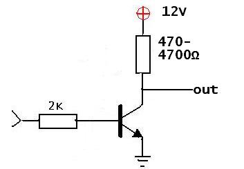
it seems i need to use a transistor on the output of the arduino to the gauge, as it'll be producing a 5volt signal, and the gauge wants a 12 volt signal, so that's another thing i have to learn (tried the way shown on some sites, npn tranny, 2 resistors, 12 volts to collector, arduino signal to base, output to gauge to emitter, but i am getting the signal feeding through it even with the collector power removed, so i've not even managed to do that right)
Can someone point me to a sketch i can copy and paste into the arduino which will make it output the 1-300Hz square wave signal at 50% duty cycle, i can then study it and figure out how it's working,
i have some 10k and 22k pots, so can use them to vary the frequency.. but would really like to use the computer to vary it, or a sketch that sweeps from 1 to 300Hz and back again,
just so i can prove the gauge works fully, and i can see i'm beginning to get somewhere, and move onto the next part which is getting the data from the simulator to the arduino.