
Probably lots of us have poked at an LCD from a clock or wherever and wondered what it would take to drive it. I’ve even taken a multimeter to one to see what the voltages looked like. I never got far doing this but I did break some lcds.
After a lot, a lot, of reading and googling around I discovered the two issues:
Most LCDs that you see around are multiplexed. For something like a clock with 7 segment digits, there’s a set of 4 backplane connectors that connect to the same parts of each digit and a set of segment connectors that connect to one particular digit; and LCDs require an AC voltage to drive them – the segment will be visible if it gets a voltage of more than 2V relative to a backplane but that voltage can be positive or negative and it HAS to even out to zero over a few tens of ms.
The result, when you look at waveforms is something like this with the backplanes and segments dancing around multiple voltage levels.

The best general reference on LCDs I found was http://ww1.microchip.com/downloads/en/AppNotes/00658a.pdf. That shows how they’re connected and driven. I later found an atmel application note http://www.atmel.com/dyn/resources/prod_documents/doc8103.pdf that shows you how to drive a multiplexed LCD with the avr’s digital I/O pins.
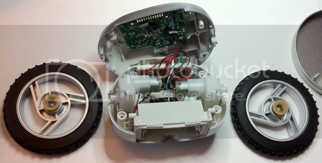
I had all this stuff percolating when I came across these little runaway alarm clocks for $2.50 in our local Staples. I took one apart finding great little motors, wheels with tires, a battery holder, and an LCD setup that looked like it would be easy to get test probes on and inject signals into.


By the way, I used to think those elastomeric connectors between an LCD and circuit board were from the devil but they're actually great for hacking. I did what I’ve done before and used little bits of post-it notes to insulate the connectors from the circuit one at a time and identify the eight segment and four backplane pins. With a scope I was able to see the typical stair-step voltages on the backplanes and segments. I drew myself many many little signal diagrams and built a spreadsheet and finally a segment/backplane diagram.

The segments turned out to be particularly easy to understand. The leftmost digit could only be 1 or blank and each of the other digits needed two segment pins: sort of for the left side of the digit and the right side. For my proof of concept I’m only actively driving one digit so I only need two segment pins.
Armed with this and the info from the application note I built a proof of concept driver. To get three voltage levels for the backplanes, I tied each of the pins to ground through a 33K resistor. If I set the arduino’s pin as output it could easily pull that to VCC or 0 and, if I set the pin to input with the pull-up resistor enabled I got a nice balance at ½ VCC. I used a 3V supply to run the AVR chip because the highest voltage I’d seen driving the LCD was around 3V.

The software feels clumsy to me but it proves the concept. The main loop just sets the single digit to be displayed and repeatedly calls the display driver. The display driver keeps track of millis() and every 4ms it advances a state counter. Each state from 0-7 defines a half cycle for one of the backplanes: backplane 1 in states 0 and 1, backplane 2 in states 2&3, backplane 3 in states 4 and 5, and backplane 4 in states 6 and 7.
I have a particular application in mind for this and I’ll use a timer interrupt to better separate the functions.
#include <Streaming.h>
#define cout Serial
#define endl '\n'
const int BP1=7, BP2=9, BP3=8, BP4=10; //backplanes
int S1=11, S2=6, S3=12; //segment outputs.  S1 is always blanked, S2&3 are driven

void setup()
{
  Serial.begin(19200);
  cout <<"Hello from the clock LCD test mule \n";
  pinMode(S1,OUTPUT); pinMode(S2,OUTPUT);pinMode(S3,OUTPUT); //segments are live
}

void loop(){
  int displaydigit= (millis()/1000)%11; //test pattern cycles from 0 to 10
  drivelcd(displaydigit);
}


void drivelcd(int digit){ //drive the LCD to display a digit
  //each of the LCD backplanes is cycled low then high for 4ms while the others are held at a middle-voltage
  //the segments are lit by setting them opposite to the active backplane
  //each bit in the digit segment table below defines the state of a segment for a particular backplane for that digit
  //the segment 2 bits are first then the segment 3 bits
  //e.g. for a 0(the 1st element) segment 2 is on for backplanes 2 and 4 (0101) and segment 3 is on for all of them(1111)
  const unsigned char dst[]={0b01011111,0b00000110,0b00111101,0b00101111,0b01100110,0b01101011,0b01111011,0b00001110,0b01111111,0b01101110,0b01111110}; //digits 0-A
  static int stateprev=8; //tells us when we change states
  int statenow=(millis()/4)&0x07; //cycles from 0-7 changing every 4 ms
  if (statenow!=stateprev){ //if the state has changed
    //reset backplane pins to input and activate the pull-up resistors
    pinMode(BP1,INPUT); pinMode(BP2,INPUT);  pinMode(BP3,INPUT);pinMode(BP4,INPUT);
    digitalWrite(BP1,HIGH);digitalWrite(BP2,HIGH);digitalWrite(BP3,HIGH);digitalWrite(BP4,HIGH);
    switch (statenow) {
      case 0:
        pinMode(BP1,OUTPUT); digitalWrite(BP1,LOW); //activate backplane 1 for 1st half of its cycle
        digitalWrite(S1,LOW); //ensure segment 1 stays blank
        digitalWrite(S2,(dst[digit]&0x80)>>7); //activate segment 2 if needed
        digitalWrite(S3,(dst[digit]&0x08)>>3); //activate segment 3 if needed
        break;
      case 1:
        pinMode(BP1,OUTPUT); digitalWrite(BP1,HIGH); //set BP1 2nd half of its cycle
        digitalWrite(S1,HIGH); //ensure segment 1 stays blank
        digitalWrite(S2,!digitalRead(S2)); //toggle segment 2
        digitalWrite(S3,!digitalRead(S3)); //toggle segment 3
        break;
      case 2:
        pinMode(BP2,OUTPUT); digitalWrite(BP2,LOW); //set BP2 1st half of its cycle
        digitalWrite(S1,LOW); //ensure segment 1 stays blank
        digitalWrite(S2,(dst[digit]&0x40)>>6); //activate segment 2 if needed
        digitalWrite(S3,(dst[digit]&0x04)>>2); //activate segment 3 if needed
        break;
      case 3:
        pinMode(BP2,OUTPUT); digitalWrite(BP2,HIGH); //set BP2 2nd half of its cycle
        digitalWrite(S1,HIGH); //ensure segment 1 stays blank
        digitalWrite(S2,!digitalRead(S2)); //toggle segment 2
        digitalWrite(S3,!digitalRead(S3)); //toggle segment 3
        break;
      case 4:
        pinMode(BP3,OUTPUT); digitalWrite(BP3,LOW); //set BP3 1st half of its cycle
        digitalWrite(S1,LOW); //ensure segment 1 stays blank
        digitalWrite(S2,(dst[digit]&0x20)>>5); //activate segment 2 if needed
        digitalWrite(S3,(dst[digit]&0x02)>>1); //activate segment 3 if needed
        break;
      case 5:
        pinMode(BP3,OUTPUT); digitalWrite(BP3,HIGH); //set BP3 2nd half of its cycle
        digitalWrite(S1,HIGH); //ensure segment 1 stays blank
        digitalWrite(S2,!digitalRead(S2)); //toggle segment 2
        digitalWrite(S3,!digitalRead(S3)); //toggle segment 3
        break;
      case 6:
        pinMode(BP4,OUTPUT); digitalWrite(BP4,LOW); //set BP4 1st half of its cycle
        digitalWrite(S1,LOW); //ensure segment 1 stays blank
        digitalWrite(S2,(dst[digit]&0x10)>>4); //activate segment 2 if needed
        digitalWrite(S3,(dst[digit]&0x01)>>0); //activate segment 3 if needed
        break;
      case 7:
        pinMode(BP4,OUTPUT); digitalWrite(BP4,HIGH); //set BP4 2nd half of its cycle
        digitalWrite(S1,HIGH); //ensure segment 1 stays blank
        digitalWrite(S2,!digitalRead(S2)); //toggle segment 2
        digitalWrite(S3,!digitalRead(S3)); //toggle segment 3
    }
  stateprev=statenow;
  }
}