Hello!
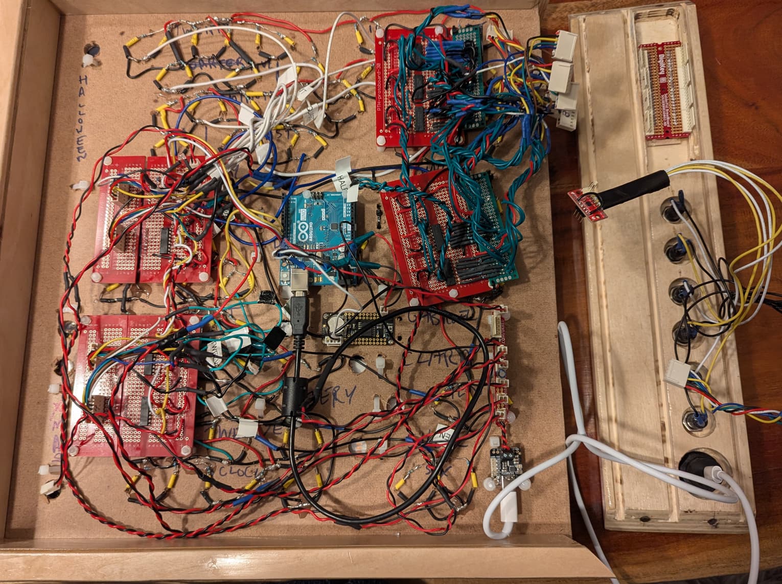
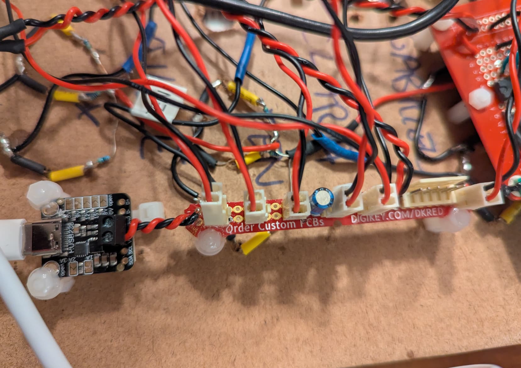
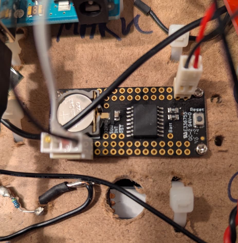
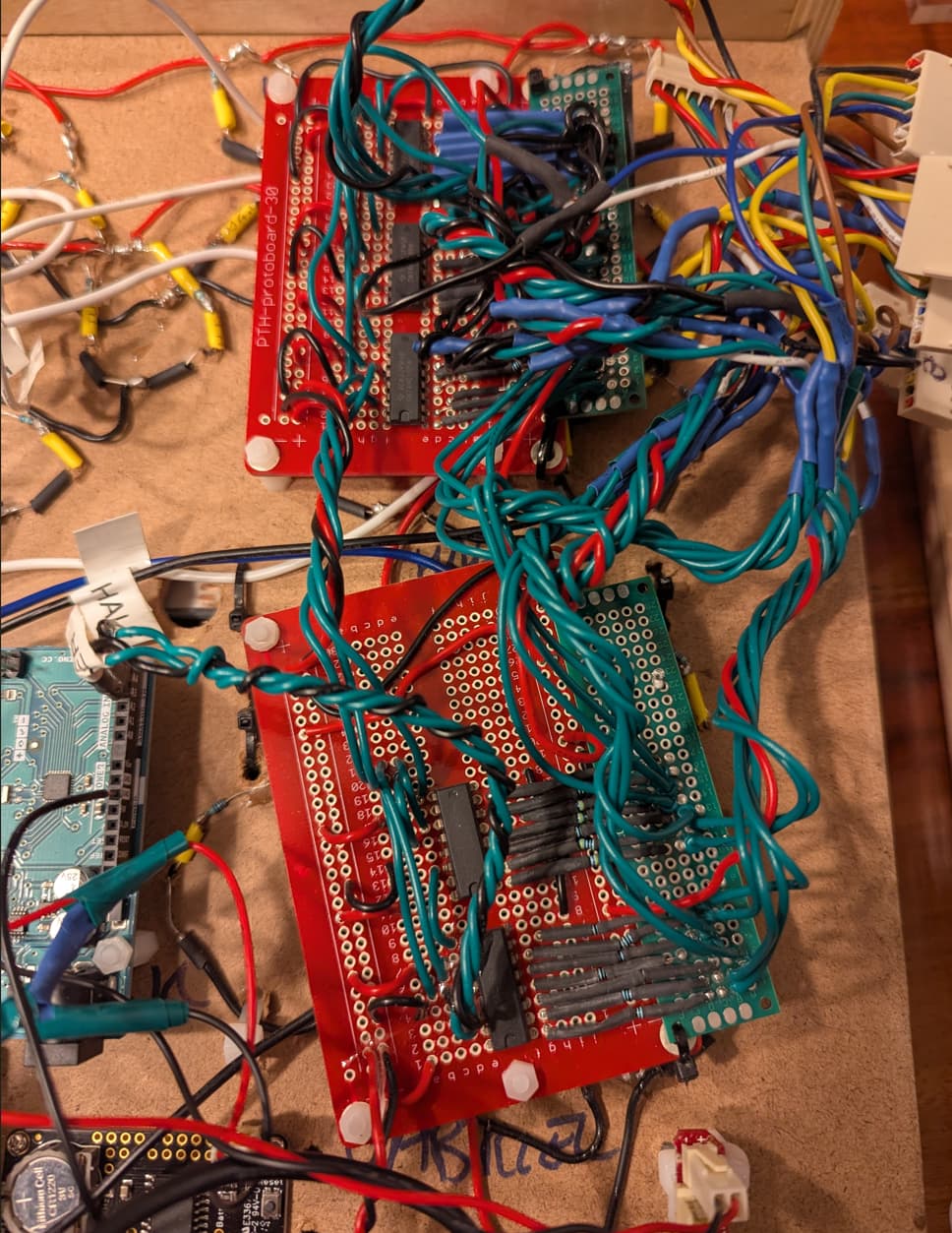
I'm trying to make a clock with an Arduino Uno, and a DS3231 RTC featherwing (Pinouts | DS3231 Precision RTC FeatherWing | Adafruit Learning System). The clock will display words through white LEDs controlled by 4x 74HC595 shift registers, and on a person's birthday serial-controlled RGB neopixel LEDs will be illuminated. I've tested the components separately from one another and they seem to work as expected. I'm powering everything separately on 5V provided by HUSB238 (Adafruit USB Type C Power Delivery Dummy Breakout - I2C or Fixed [HUSB238] : ID 5807 : Adafruit Industries, Unique & fun DIY electronics and kits). I also have a MUX (4051) for 6 control buttons, and another set of 5x 74HC595 shift registers for 7-segment displays, but those aren't in use for the stage of integration testing I'm currently doing. edited to add rough circuit diagram below

Now that I'm putting everything together (the RTC, the white LEDs + the RGB LEDs) and doing integration testing, I'm seeing some weird behaviour. Whenever I have more than about ~7-8 RGB LEDs illuminated simultaneously with the white LEDs, the serial readout of my RTC gets very strange:
Initializing RTC...
Checking if RTC lost power...
====================================
2025/10/31 5:32:30
IT IS HALF PAST   FIVE (hours) OCLOCK
Sleeping...
====================================
2025/24/20 25:10:0
IT IS TEN (minutes) MINUTES PAST  ONE OCLOCK
Sleeping...

2025/0/10 14:18:0
IT IS TWENTY MINUTES PAST  TWO OCLOCK
Sleeping...
====================================
2025/0/12 10:0:0
IT IS     TEN (hours) OCLOCK
Sleeping...
====================================
2025/0/0 12:0:0
IT IS     TWELVE OCLOCK
Sleeping...
However, if I reset the arduino, I see the initial readout from the RTC is maintained (and I don't see a message indicating the RTC lost power and is being reset to time of the last sketch compilation), so I don't believe the RTC itself is compromised or losing its time. My suspicion at this point is noise on the SDA/SCL, or instability of the 5VDC. Measuring with a DMM indicates the 5V isn't dropping, so I don't believe it's related to current starvation. I've also tried putting a 0.1uF capacitor on the 5V rail to smooth out voltage ripple, but the same behaviour persists.
Some forums/sources I've read suggest putting pull-up resistors (5-10k) between the SDA/SCL lines and the 3.3V line -- but my understanding is that the DS3231 RTC featherwing already HAS pullup resistors, so I'm at a loss as to what else to try and what might be the root cause of this issue.
Thanks in advance for your help. I'll post my code below for completeness but I think the likely problem is outside the code. There are some subclasses which I haven't included but can upon request if it's material to the solution/debugging.
#include "RTClib.h"
#include "TimeWords.h"
#include "RainbowWords.h"

RTC_DS3231 rtc;

const int selectPins[3] = {3, 4, 5}; // S0~3, S1~4, S2~5
const int zInput = 2;

// shift register pins for the white words
const int whiteLedsClockPin=12;
const int whiteLedsLatchPin=11;
const int whiteLedsDataPin=13;

// shift register pins for the side-panel 7-segment display
// A0-A5 can be called by D14-19
const int segmentClockPin=19;
const int segmentLatchPin=18;
const int segmentDataPin=17;

TimeWords timeWords(whiteLedsClockPin,whiteLedsLatchPin,whiteLedsDataPin);
RainbowWords rainbowWords;

void setup() {
  // select pins for MUX
  for (int i=0; i<3; i++)
  {
    pinMode(selectPins[i], OUTPUT);
    digitalWrite(selectPins[i], HIGH);
  }
  pinMode(zInput, INPUT_PULLUP); // Set up Z as an input

  // white LED shift register pin declarations
  pinMode(whiteLedsClockPin,OUTPUT);
  pinMode(whiteLedsLatchPin,OUTPUT);
  pinMode(whiteLedsDataPin,OUTPUT);

  // 7-segment shift register pin declarations
  pinMode(segmentClockPin,OUTPUT);
  pinMode(segmentLatchPin,OUTPUT);
  pinMode(segmentDataPin,OUTPUT);

  rainbowWords.initialize();

  // serial console setup
  Serial.begin(9600);
  #ifndef ESP8266
    while (!Serial); // wait for serial port to connect. Needed for native USB
  #endif

  // Real-time clock initialization for DS3231
  Serial.println("Initializing RTC...");
    if (! rtc.begin()) {
      Serial.println("Couldn't find RTC");
      Serial.flush();
      while (1) delay(10);
    }

  Serial.println("Checking if RTC lost power...");
    if (rtc.lostPower()) {
      Serial.println("RTC lost power, let's set the time!");
      // When time needs to be set on a new device, or after a power loss, the
      // following line sets the RTC to the date & time this sketch was compiled
      rtc.adjust(DateTime(F(__DATE__), F(__TIME__)));
    }
}

void loop() {
  Serial.println(F("===================================="));

  DateTime now = rtc.now();

  Serial.print(now.year(), DEC);
  Serial.print('/');
  Serial.print(now.month(), DEC);
  Serial.print('/');
  Serial.print(now.day(), DEC);
  Serial.print(F(" "));
  Serial.print(now.hour(), DEC);
  Serial.print(':');
  Serial.print(now.minute(), DEC);
  Serial.print(':');
  Serial.print(now.second(), DEC);
  Serial.println(F(""));

  timeWords.updateAllTimeWords(now);
  rainbowWords.updateAllRainbowWords(now);

  Serial.println(F("Sleeping..."));
  delay(1000);
}