It has been mentioned from time to time that the popular DS3231 RTC module (aka the ZS-042 module) has to be modified for low power use - disable the "charging circuit", remove the power indicator LED or its resistor. But going beyond that, I ran across a video by Ed Mallon which says the DS3231 idles at a much lower current when powered from the chip's Vbat pin instead of its Vcc pin. There's no explanation of why that should be the case, but I've confirmed it's true.

When nothing is happening on I2C, I measure 90uA on the Vcc line at 3.3V, or 125uA at 5V. That's with the SDA, SCL, INTSQW and 32K pins all high, so none of that current is being sunk through the pullup resistors. But if Vcc is not powered, the coin cell battery takes over, and the current there drops to 1.25uA, with a small blip every 10 seconds, which I assume is the temperature correction thing. The thing is - everything still works normally, including the alarm interrupt and I2C.
Mallon takes advantage of this by literally lifting the Vcc pin (pin 2), and using the charging circuit for power, which is already connected to the Vbat pin (pin 14), The battery is still there too, but he cuts that trace and inserts a diode from the coin battery to pin 14 to protect the battery from what may be 5V charging current. I've attached the original ZS-042 circuit, and Mallon's modified version.
This is all fine, but I have a problem with the reduced battery life the diode voltage drop would produce if the device is going to spend any significant time on coin battery power. And his mod seems a bit fiddly to me. But if you never switch to coin battery power, even when sleeping, you get very low idle current, and that current is provided by the main project battery, not the coin cell, and in that case the battery diode drop wouldn't make any difference.
I've also attached an alternate mod circuit that doesn't require any pin lifting or added diodes, just cutting traces. The Vcc header pin on the module would be powered from a GPIO pin, which would be raised only when you need to do something with the RTC. At all other times, including when sleeping, the GPIO would be switched to output low, or to input mode with no pullup resistors. You would also have to disable any pullup resistors that might be enabled on the processor's I2C lines. And of course the charging circuit would need to be disabled, as would be needed even with no mod at all.
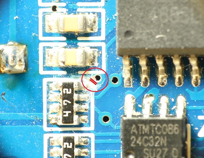
If the alarm function on INTSQW is going to be used, then the connection of that pin to its pullup resistor would also need to be cut. That's because the pullup resistor is connected to Vcc, which wouldn't be pulling up if the GPIO is not high. So instead you would enable the processor's internal pullup resistor on the interrupt line. This would require cutting the trace from the top resistor of RP1 to the via right next to it.
The alternate mod would have the I2C heavy lifting current provided by the main project battery, but at all other times the coin cell would be powering the chip. But of course that's only at 1.25uA, so the coin cell would still last a long time. And there would be no diode drop in the battery line.
The alternate mod would be particularly appropriate if the INTSQW pin is going to somehow power up the processor when the alarm triggers - you would almost certainly have to disconnect the INTSQW pullup resistor anyway, and the RTC would be on the coin cell battery anyway when the processor is powered down.
The large difference between powering from Vcc and powering from Vbat matches what the datasheet says, but I just hadn't been looking for that, particulary since it doesn't make much sense to me. Either Vcc should also idle at 1.25uA, or some functions should be disabled on Vbat. But it seems everything still works on Vbat, so it's puzzling what's drawing that additional 89uA when idling on Vcc.