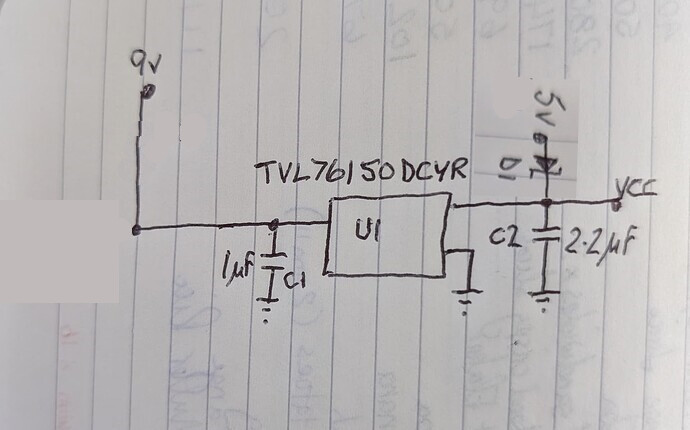
I'm about to design an adaptor board that will have a ProMini and a DFPlayer module attached to it. The ProMini will be controlling a selection of LEDs through a transistor array and also controlling the DFPlayer. My "client" has requested a choice of powering the assembly via a 5v USB connector or 9v battery.
As a hobbyist and not a pro, I'm not too sure what schottky diodes I should be using (D1 and D2) in the attached sketch.
Is this, in fact, the best way to supply power to the 5v TLV761 which will be supplying both the ProMini and the DFPlayer but not the LEDs (they have a separate supply).
I know the ProMini can take 2.5v to 16v, but I need a higher rated 5v power supply to the DFPlayer as it could be driving a 3w speaker.
Non-critical. SS110 is a common type. There are hundreds more that will work fine.
And USB can certainly go over 500mA and that's not just a theoretical observation. Any $2 generic Chinese phone charger will do it.
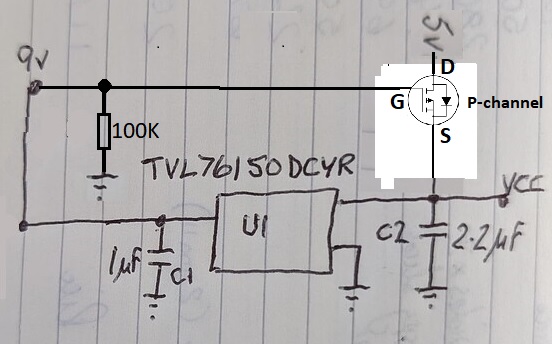
Just for completeness, this might work to eliminate the voltage drop:
However,
If both supplies are present, the 9V will supply all the current, which may not be what you want.
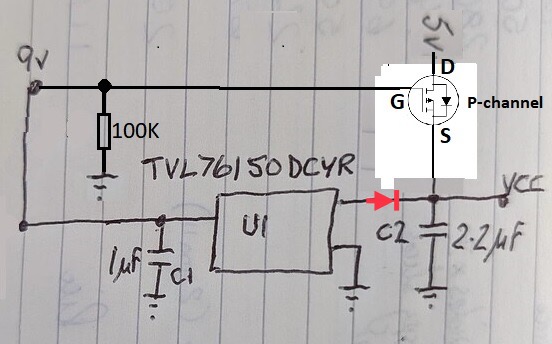
I don't know if any current will flow back through the regulator when voltage is applied at its output, but its input is grounded. You would need to test that.
Yes, the datasheet suggests the diode would be needed to block reverse current. But then really you might as well use two schottky diodes, and forget about the mosfet. You'd end up with 4.7V Vcc on either source.
I wonder if he could move the diode over to the input of the regulator and get the reverse current protection needed. That would leave the output voltage at 5V, and wouldn't actually reduce efficiency since he's dropping 9V to 5V anyway. I guess in theory battery life would be reduced because of the diode voltage drop, but I don't think the battery would have much left at that point anyway.
It's a linear regulator so it can't output a voltage equal to or greater than the input voltage.
In the data sheet you will see a dropout voltage (Vdo) spec. It can be as high as 1.6V, that means the the input voltage should be at least 5V+1.6V = 6.6V
Well the naximum quiescent current is 100uA.
If you have a good 9V alkaline battery it should have a rating of about 450mAh.
So with a drain of 100uA the battery will go completely dead in about 450mAh/100u = 4500 hours. Actually less hours because the battery is useless once the voltage drops below 6.6V, so figure maybe half that, 2250 hours = 93 days.
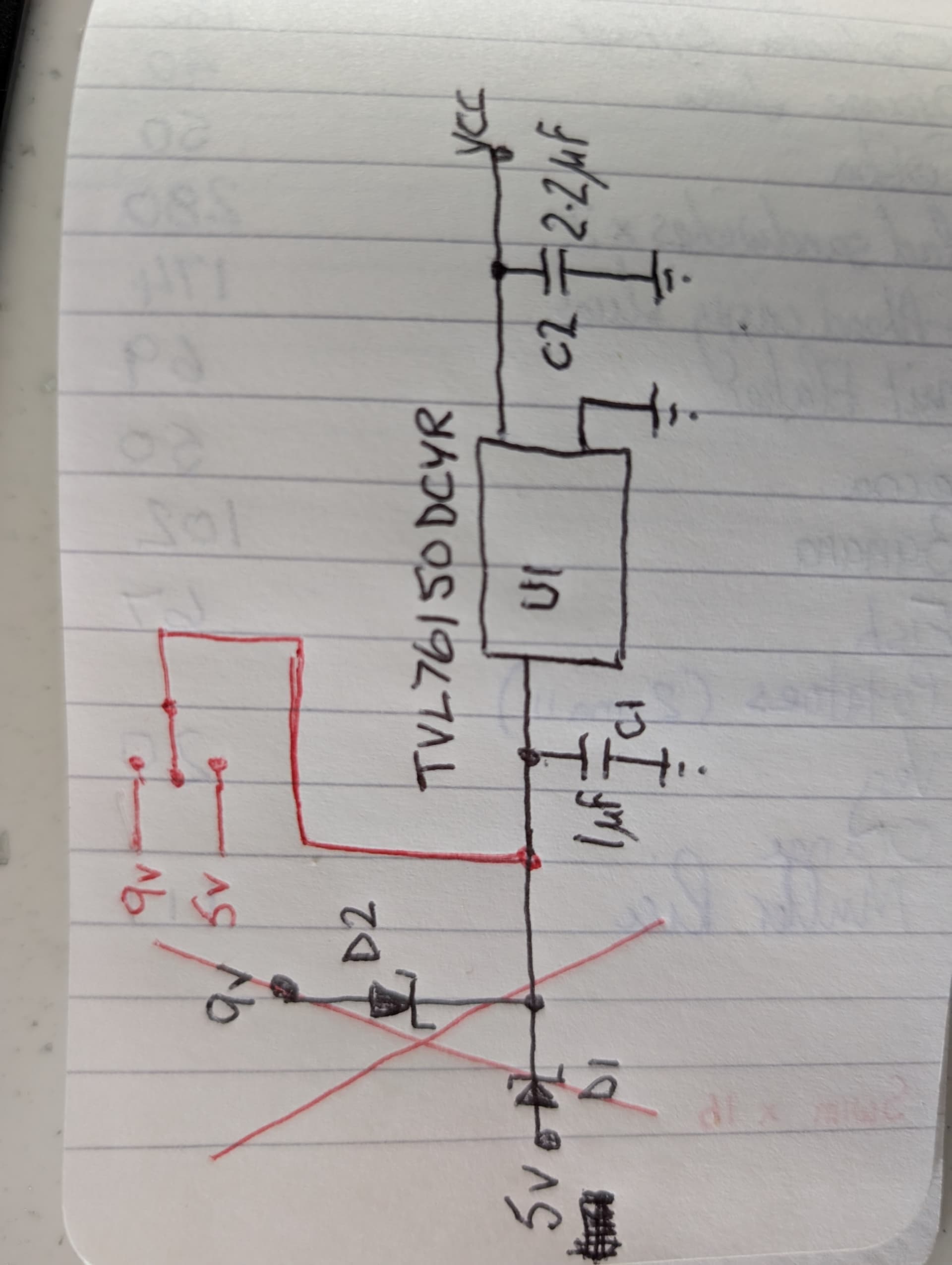
You could use a double pole 3 position switch to switch both the input and output of the regulator