TomGeorge:
Hi,
How do you expect the LEDs to work?
Double check the number and PINOUT of the 2N2222 as there are 2N2222A and others with different pinout configurations.
Pull your project out of the motorcycle and put it on the bench.
Replace the relays with LEDs and see what happens, REMEMBER to use current limit resistors with your LEDs.
Where is the rest of your circuit, how do you start the sequence?
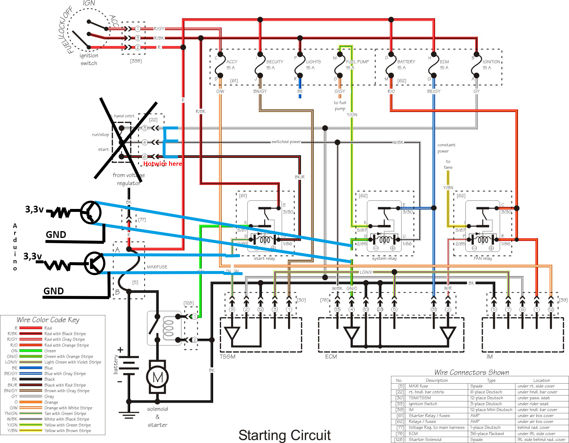
Can please post a copy of your complete circuit, in CAD or a picture of a hand drawn circuit in jpg, png, especially showing your power circuit?
Hand drawn picture is usually the easiest and quickest.
How are you powering the UNO, do you have bypassing on the power supply to the UNO?
As suggested, place back EMF protection diodes across the relay coils.
PLEASE post your code....
Please read the post at the start of any forum , entitled "How to use this Forum".
OR
http://forum.arduino.cc/index.php/topic,148850.0.html.
Then look down to item #7 about how to post your code.
It will be formatted in a scrolling window that makes it easier to read.
Tom.... 
Thanks for the suggestions.
I really regret that I put a LED there. It was just a symbol for some other things that I dont know what it is in it, a TSSM and a ECM. The diagram didnt have symbols for that, but now I understand that i should have put someting else there then a LED.
Though I beleve it goes directly to ground, maybe just a inicator that register that fulepump is on etc.
The code is really secunday here, its just to turn the DP on at this point. I will build this after i figured out this mess.
int FuelPump = 13;
int Ignition = 12;
int inPinFuel = 6;
int inPinIgnition = 7;
int valFuel = 0;
int valIgn = 0;

void setup() {
  pinMode(FuelPump, OUTPUT);
  pinMode(inPinFuel , INPUT);
  pinMode(Ignition, OUTPUT);
  pinMode(inPinIgnition, INPUT);
}

void loop(){
  valFuel = digitalRead(inPinFuel);
  valIgn = digitalRead(inPinIgnition);
  if (valFuel == HIGH) {
    digitalWrite(FuelPump, HIGH);
  } else {
    digitalWrite(FuelPump, LOW);
  }
  if (valIgn == HIGH) {
    digitalWrite(Ignition, HIGH);
  } else {
    digitalWrite(Ignition, LOW);
  }
}
The ESP32 is powerd by USB from computer, does this matter? I have not tried changing that, do you think the outcome could change with other powersupp?
I could try disconnect the bike and bench it with LEDs insted of relays to try it out. But still, in my head it should work like i have drawn it in the diagram.