Above my pay grade, but looking at the transistors as perfect switches my "analysis" suggests there is room for improvement.
By turning only Q16 on, a current will flow one direction and be reduced by the equivalent of 100 ohms in series.
By turning both Q15 and Q16 on, the coil will see the full 5 volts, with the current flowing in the opposite direction.
So it will switch.
By turning only Q15 on, there will be no current in the relay.
So you can have coils not cooking.
This set of facts cloud be addressed by software which woukd all be within a few lines of where the relay switching is happening.
I reiterate this is posted in the hopes that an internet rule applies: by posting a wrong or misleading answer one will soon be slam/corrected by anyone still reading this thread who knows better, or can agree, but more importantly by someone who can suggest a proper circuit that would actually work better.
H-bridges have been mentioned, it's more parts but is the way to control bidirectional current in DC motor circuits.
This circuit is, I believe, where you started, note the 47 ohm resistors so the coil gets a good current. Your relays' coil resistance is higher, so you "got away" with 100 ohms.
TBH this circuit and your original by implication always seemed to me like getting away with a dodgy design.
I think I'm at my "uncle" phase... too far in to give up, but these single coil latching relays just keep giving me issues. I'll throw an order for the dual coil versions tomorrow.
From what I can tell, I can just have each coil connected to ground at all times, and use my opto/transistor combos to trigger the coils as needed... no inversions, nothing weird - just pulse as needed.
It doesn't change the code or the design - just makes it easier to work with - unless one of y'all thinks that's not the ticket... but Mouser's got em, so I just gotta get over being wasteful... sigh
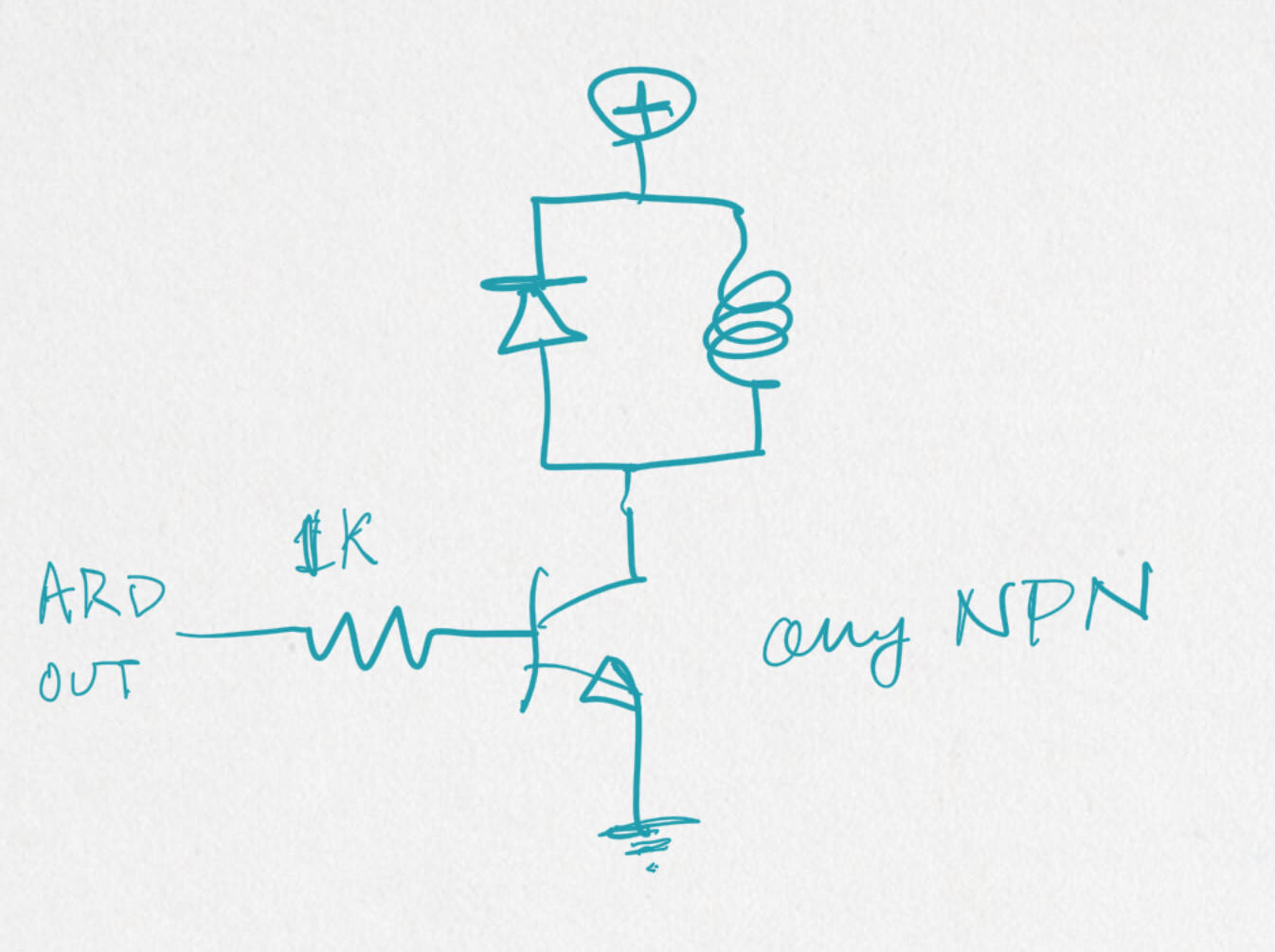
A TO-92 MOSFET two resistors and a diode make a simple driver.Lose the optos, no need.
See
The usual circuit has the BJT transistor or MOSFET with the bottom side to ground and the relay between Vcc and the top side.
I bought a lifetime supply of 2N3904 NPN transistors, a more modern choice is the 2N2222. I can't say for sure the 2N7000 MOSFET work work perfectly well.
It is just like driving two relays. Software written to not pulse both coils at once.
I did see many single coil ideas, someone with their finger on the pulse of what's available today would have to say if any one makes more sense than another. Some took lotsa parts, and some were kinda spendy, so.
I have all of these on-hand in some capacity - the s8050 is an alternate to the 2n3904 (I think it handles more current?), and I have a ton of those, so... we'll see what works when it all comes through. At least it's a plug/play with my breadboard setup, so I don't have much to do there.
At this stage, that's the goal - whatever works without getting too hack-y. Thought I'd found my ace with the NOT gate. Alas, this is why you ALWAYS test and breadboard. #learning. #applying.
THAT ASIDE - my 5v supply problem was a bad 7805, so that's fixed, and the NeoPixel 5mm LEDs now work perfectly after changing them to NEO_RGB in the code. You weren't kidding when you mentioned how bright they are - I put them at 50 (out of 255!), and that still might be too much.
Updated wokwi - it's working well, it's looking good, no compiler warnings (the NeoPixels are off in the wokwi, but normal in real life). Again, thank you for the help!
Going dark while I await the new dual coil relays, but will keep an eye on all the things in the meantime.
Sounds good. The UA may pound on the code more with hope of catching some obscure defect than plans to make any further adjustments.
I see eepromToRelays() and in case it isn't obvious, there may be one or two more places where an okDelay() might be placed, trying to avoid any noise from the switching but keeping it all as brief as possible.
relays came early - I think they'll work great - tested them with some LEDs and all I have to do is pulse one side or the other - no inversions needed, so that's awesome.
But also - I cannot get anything to trigger them in my circuit. Optos, transistors, mosfets... nothing I have will get more than 2ish volts to the relay pins.
Am I missing something? I only need to send 5v to pins when I need them for a short time. This setup will only send 1.7v to the pins:
I then did away with the opto completely and just used the transistor - 2.2v using the buffer gate.
changed the resistor values - nothing did much.
I have some s8050s and then tested the 2n3904 - no dice.
the mosfets didn't fare much better - 2n7000.
I'm... struggling. Is it a different optocoupler I need? Should I be giving more than 5v to these devices? I looked up every way the internet says to power these things, and all of those have 5v steady to the pins when active - I'm this close to just driving them right from the Arduino...
Sry, I should have linked to this, it has FET and BJT circuits:
Also, pay attention - the dual coil latching relays I have are polarized, that is to say you have to put the current through a coil in the direction the data sheet says.
More Panasonics - tq2-l2-5v. When I was able to get the single coil ones working, they sounded very clear so I went with what I knew.
From my testing, they aren’t polarized, but the datasheet visual has pins 5 and 6 as GND, 1 and 10 are positive. This will work for me.
I tested the relays with 2 LEDs (one green, one red) on each throw (so 4 LEDs) - trigger pin 1 with 5v, it was the red ones, trigger pin 10 and it was green ones.
I’m possibly going to sound dumber than I ever have yet - but doesn’t the diagram above have the coils at 5v all the time? Isn’t the notion to have them at ground and pulse 5v?
I’ll give this a test tomorrow either way… I just want to be sure I’m hitting all the right notions - the internet can be tricky sometimes, hehe…
This aside, I was wondering about the NeoPixels - for effects 9-16 I was debating having those a different LED color. Obviously they come from the same pin, but I think you can set them based on number? It’s less clear about this, so if you have any advice, I’m all ears (or eyes? Fingers? I’ll stop…)
I should not have said "try", I should have said "use" that circuit. If it doesn't work, the only experiment would be to use a 470 ohm resistor. If that doesn't work, we have two options.
As for the Neopixel, use the setPixelColor() method, which take two arguments, the pixel number 0 to N - 1 where N is the number of pixels on the strip, and a color.
Since you've been doing this all along, or have seen it being done at least, I am at a loss to supply additional help.
pLED.setPixelColor(whichPixel, whatColor);
whichPixel is an int, whatColor is an unsigned long. Program logic determines the values of those variables.
If it is sunny make the pixel that represents the sun bright yellow. Then hope she will want to go to the beach soon-ish.
Tried this - Doesn't work. Used a 2n3904 and a s8050 - same result both times. Also swapped the Zeners for 4148s - also no dice. I can't get more than 2.3v to any given pin at time of switching.
When I hit a button that has a stored effect:
pin 1: 5v resting - 2.3v on button press
pin 5: 5v resting - .5v on button press
pin 6: 5v resting - 2.3v on button press
pin 10: 5v resting - 2.3v on button press
I looked up "transistor as a switch" to see if that could net something (same as your schematic, but attaching additional 1k from base to GND) - still not working:
pin 1: 5v resting - 2.3v on button press
pin 5: 0v resting - .5v on button press
pin 6: 5v resting - 2.3v on button press
pin 10: 0v resting - 2.3v on button press
Perhaps I'm connecting the flyback wrong? The flyback diode should be 1 diode to a coil, with the line facing the positive coil pin, right? So pins 1 and 5 get one, then pins 6 and 10 get one, yes?
tested the transistors and they aren't blown so far as I can tell. Used new/different ones, same result.
I'm supplying everything from 5v supply, which is steady at 5v from the 7805, and that's being fed by a 9v 340ma power supply.
went back to the optos to try that out - the PC817 seems to take 5v and turn it into 2.3v.
When I test these in isolation (away from the relays), I get well into 4v in almost any incarnation I've tried - logic gate buffer, transistor as a switch - but with the relays, I don't know if the coil resistance is messing with me or what. I'll keep doing some research, but this is... certainly perplexing! lol.
The relay coil current is 40 mA so the simple circuit should work with 1K and no better with 470 ohms.
Use a regular diode, not a zener. The cathode (banded end) should go to 5 volts and one end of the coil, the anode to the other end of the coil.
Use a simple sketch like blink from the IDE. Put a regular LED with a series limiting resistor in the circuit instead of the relay coil. Obvsly, hope, this LED should have its anode connected to 5 volts.
That LED should blink.
Extend the simple sketch to two copies of the transistor-driven LED circuit.
pulse 1, all outputs off, puke 2, all output off, repeat
just using delay() for all the timing.
The LEDs should blip alternately with lotsa time between them.
I did take this into account, but still wanted to test the voltages - whether it's on all the time or just for a pulse, I still need at least 3.75v to one pin and 0v to the other for each coil to trigger, which isn't happening. It's either 5v at both, or 2.3v at both, or 2.3v and .5v (not enough to trigger).
this is where the optos come in handy because they pulse signal since the Arduino is always HIGH but the other pin is connected to 5v - so they're off until the Arduino goes low. Either way, I get the same result from that - only in pulse format.
something is dropping the voltage, and I can't figure it out... will sleuth a bit more - take one instance out of circuit for its own thing using my Uno or something is a good idea... I'm finding some results in search, but their fixes are things I already have going (my pins are set for output).
OK I dragged a dual-coil module I made some years ago - never mind how long precisely - and it has
an Omron G6AK-234P 5 volt dual coil relay with very similar specifications
2x 2N3904
2x 1N914 switching diodes which I would do better at now, but seem to have done their job
2x 8K2 base resistors, which I would def lower doing it over, as it means I am not driving the transistor to saturation and am relying on it's current amplification capability.
a LED and 470 ohm series current limiting resistor switched by one of the DPDT sections for feedback
So maybe marginal but functioning well in the device I removed it from just now since years.
I put in there long ago may be your one place to make the drive signals for the dual coil latching relays correctly energize one or the other coil and then place both back to not-energized.
# define rHot HIGH
# define rGnd LOW
But srsly, test with a dumb sketch and a few pushbuttons.
Brilliant - I needed to change it in the setup of the relays, but otherwise it flipped everything beautifully - and it still works as needed. had to reverse all the LEDs, but the .json worked beautifully to do that quickly. I was also able to simplify the relay setup.
I rebuilt my breadboard using your schematic for each pin above - works like a charm. Everything hits when it needs to, nothing lags, and everything is good. Why did I jump into this instead of a small thing like you suggested? Well... I know I won't have time this weekend to rebuild it, and I'd have to rip up a breadboard to set anything else up (I have 4 breadboards, and this is taking up all of them). So... I went rogue - and it works.
4.9v at each coil pin unless I need to change effects, and then it goes to 0v for a short period (6ms got it every time) until it then goes back to 4.9v. I left it on for a while to see if anything weird would happen if I just let it sit a while and then hit a button now and then. Nothing weird, and worked every time. (per convo, I mistook what "cooking" meant - but I feel better about the dual coils anyway - though the not gate inverter does work for the single coils).
So. That's... something. Sorry for the goose chase cause I assumed something. part of the learning curve, I guess?
So now I can spend my weekend doing weekend-y things. (who am I kidding? this thing has taken over my life, hehe... )