Hi, I'm electronic beginner and I have my own Arduino.
Which is better to use Electron or Conventional flow for learning basic electronics?
Last night, I researched on internet about optocoupler 817C and it's collector current is 50mA max, however
do I need to add resistor to reduce current for Collector-Emitter?
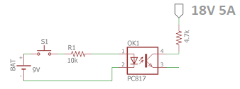
I looked on internet and the picture, it don't showed me the ampere of 18V, and it just showed me 18v only
I checked 817 datasheet and it said "Max volt is 80v for Collector-Emitter & collector current is 50mA".
If 5A ampere current passes from Collector-Emitter will blow?
Everything you see in electronics uses conventional current flow unless specifically stated otherwise. It probably matters for chemistry as you have ions and electrons as charge carriers, but for everything else use conventional current.
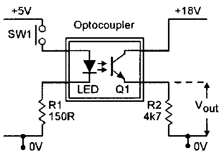
With an opto coupler the transistor current is a function of the LED current, there will be a current transfer ratio specified. Suppose it is 0.8 then 10mA in the LED will produce 8mA in the transistor. The resistor is so there is something to develop the output voltage across.
Which is better to use Electron or Conventional flow for learning basic electronics?
It does not matter as long as you use one consistently. I learned electronics using electron current, but I am old.
Last night, I researched on internet about optocoupler 817C and it's collector current is 50mA max, however
do I need to add resistor to reduce current for Collector-Emitter? Yes, you need a resistor to limit the collector-emitter current.
I looked on internet and the picture, it don't showed me the ampere of 18V, and it just showed me 18v only
Sorry, that makes little sense.
"Max volt is 80v for Collector-Emitter & collector current is 50mA".
That means that the load resistor (R2) minimum value is 1.6K (80V / .05A). In practice it would be much higher.
If 5A ampere current passes from Collector-Emitter will blow?
What is the load between Vout and 0V? If the max current is 50mA (0.05A) and you drive 5000mA through it, it will definitely BLOW, like a fuse. The arrows on diode and transistor symbols indicate the direction of CONVENTIONAL current flow, so that's the one to use.
To put that into perspective, if enough energy passes through the junction of a semiconductor device such as a simple generic 2n3904 npn or 2n3906 pnp transistor or an opto coupler, it can literally explode, propelling shrapnel
(the plastic blown out of the device) at very high speeds, which if it were to hit your eye , could actually imbed in''
your eyeball. I once witnessed a 2n3906 explode with such force the concave shaped shrapnel hit two walls before
it wound up on the other side of the room. The transistor had a crater in the flat face of the TO-92 package and you could see the actual metal junction inside the device. it sounded like a firecracker. This is, by the way, the reason
most electronic labs in large companies require safety glasses at all times inside the labs. If you have never witnessed such an event or are not aware that such things are possible, you would most definitely be quite startled.
Technicians, on the other hand, when they here that sound, know what it is and might flinch but are not as startled.
FYI, current is a function of voltage and resistance (V = I x R=> I=V/R) 18v/0.05A = 360 ohms. It is usually best not
to operate a device at the maximum ratings so a higher resistance would be used, (ie: 390 to 470), but if all you need is a logic signal then a 4.7k ohm resistor is used. The reason it is connected to GND is that the designer does not
want to invert the logic. Normally the pullup resistor on the collector of an optocoupler would be be connected to
+Vcc, but this results in a logic inversion because the transistor pulls the signal low when the led is on. If this logic
inversion is inconvenient, the designer puts the resistor from the emitter to GND as shown in the image, thus
resulting in 1:1 logic translation. (led on = H output signal)
Which is better to use Electron or Conventional flow for learning basic electronics?
It took me a LONG time before I really understood that...
I took electronics in high school and we used electron flow. Then I took electronics in college and learned conventional current. Then I took physics and learned electron flow again!
Electronic engineers and technicians use conventional current-flow.Scientists use electron-flow. And, if you're an engineer designing semiconductors you're thinking in terms of electron flow (and hole flow).
...I still think conventional current is "stupid" but we're stuck with it and we have to accept it! Whoever designed the schematic symbols used conventional current so there is consistency in the "electronics world"
however do I need to add resistor to reduce current for Collector-Emitter?
Yes, the resistor limits current (when the transistor is on) but it's also required because you essentially want a variable [u]Voltage Divider[/u] where one-half of the voltage divider is a transistor instead of a resistor.
A voltage divider works because of Ohm's Law, plus the fact that the same current flows through series components (one of Kirchhoff's Laws). The voltage gets divided with more voltage "across" the higher resistance.
When the transistor is off it has (nearly) infinite resistance so the voltage is across the transistor with (almost) no voltage across the resistor, and (almost) no current flows.
When the transistor is on it has (nearly) zero resistance so (nearly) all of the voltage ends-up across the resistor and current flows.
NOTE: For anyone who doesn't already know it;
ELECTRONS ARE NEGATIVELY CHARGED , SO ELECTRON FLOW IS FROM GND TO +Vcc (the little buggers are attracted to the POSITIVE terminal like 19 year old boys to girls)
CONVENTIONAL FLOW is from +Vcc to GND
We are talking about 2 slightly different things because the direction of movement of charge carriers depends on whether those carriers are positive or negative. Much of the current flow in an electrical circuit is the result of electron flow, so negative to positive in the circuit. Within electronic components there will be both electron and hole movement, so both from negative to positive (electrons) and positive to negative (holes). In an electrochemical cell there will be positive and negative ions with their corresponding direction of movement. Conventional current flow simplifies these differences and just asserts current flowing positive to negative, which is all you need for most purposes.
Hi, I'm electronic beginner and I have my own Arduino.
Which is better to use Electron or Conventional flow for learning basic electronics?
The direction of current flow is irrelevant in understanding electronics. If you think it matters then you don’t understand it yet.
I was brought up on conventional current and when I went to University to take Physics then they still used conventional flow, because in semiconductors electron flow and hole flow are simply the opposite of each other. Depending on the material’s composition one or the other will dominate in any given situation.
Fun fact, holes ( the absence of an electron ) can sometimes have a positive mass, which means an electron will have negative mass. Maybe we can have our hover boards some day.
Just to add to the mix, the assignment of a "negative" charge to an electron is also arbitrary. Someone told me, Benjamin Franklin made the call, and had a 50% chance of getting it "right", lost the bet. If he had just given the electron charge a positive sign, none of this would have happened.
"ust to add to the mix, the assignment of a "negative" charge to an electron is also arbitrary. Someone told me, Benjamin Franklin made the call, and had a 50% chance of getting it "right", lost the bet. If he had just given the electron charge a positive sign, none of this would have happened."
I thought it was agreed the proton is positively
charged.
raschemmel:
I thought it was agreed the proton is positively
charged.
Aha! That's the fun thing! If you called the lepton charge positive, a proton would indeed have a "negative" charge, the math and the universe would be copacetic.
But why shouldn't things go from negative to positive? After all, the integers do! If you don't believe me, start counting...
Grumpy_Mike:
The direction of current flow is irrelevant in understanding electronics. If you think it matters then you don’t understand it yet.
I was brought up on conventional current and when I went to University to take Physics then they still used conventional flow, because in semiconductors electron flow and hole flow are simply the opposite of each other. Depending on the material’s composition one or the other will dominate in any given situation.
Fun fact, holes ( the absence of an electron ) can sometimes have a positive mass, which means an electron will have negative mass. Maybe we can have our hover boards some day.
Effective masses are complex (there are several kinds, depending on which property you
care about) - this is advanced solid state physics and perhaps only going to confuse in this context!
They are also a property of the crystal lattice, not the particles as such.
The sign convention for electric charge was invented before the discovery of the electron, which is why
things seem backward.
If I add 4.7 Ohm will it help protect the collector & emitter?
Yes, but...
But your schematic shows 4k7 and your question says 4R7. 4k7 is reasonable, 4R7 is not.
But you need a resistor anyway so there is something to develop the output votage across. Without it the collector is tied to 18V and the emitter to 0V, no possibility of any change on the output.
You see the arrow symbol of collector and emitter at most transistors that is conventional flow?
Exactly right, and true for any component. Note that on a BJT the arrow is always on the emitter, not the collector. The direction tells you whether it is NPN or PNP (the transistor shown is NPN).