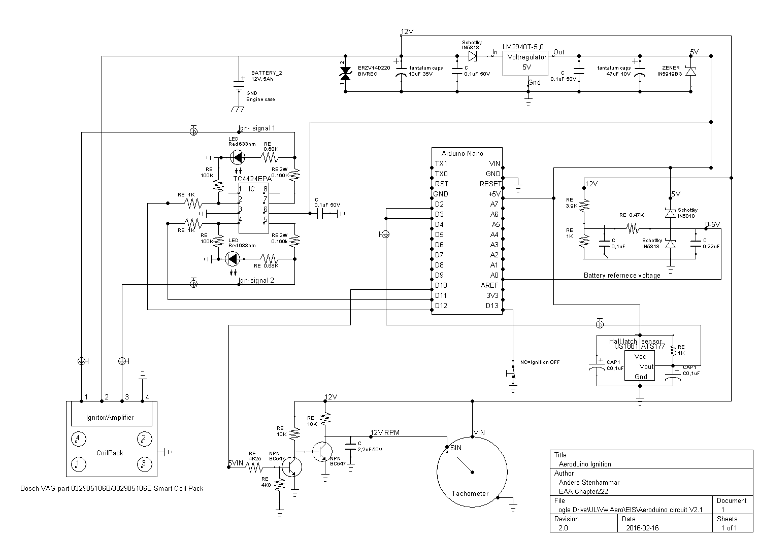
The 1n5818 diodes used in multiple areas a Schottky's, not Zeners. May help avoid some confusion
On more recent versions of this power circuit, I've moved the schottky to immediately before the regulator. This prevents the 12v source being backfed with 5v in a situation where the ignition is off but USB connected. EG
You've gotten the value of the resistors on the outputs from the TC4424 wrong, they should be around 160 Ohm, not 100k. Note also that these need to be rated for at least 1W, preferably 2W
As mentioned, the power circuit output should feed into the 5v line, not VIN
I use (and would recommend) tantalum caps rather than the electrolytics on this power circuit, but up to you.
I'd suggest bumping up the 1k pullup resistor on your tacho output circuit to 10k
Other than that, that tc4424 circuit will work for virtually all logic level ignition modules I've tested with, so that should be OK. Everything else looks like what I've used, so should be fine.
Ok thank you so much! This help is so valuable. It is so easy to do misstakes when working on this.
Yes I figured it will get hot, so I will connect a heatsink to it and mount the heatsink outside the epoxy filled metal box (isolated from ground).
The 1n5818 diodes used in multiple areas a Schottky's, not Zeners. May help avoid some confusion
On more recent versions of this power circuit, I've moved the schottky to immediately before the regulator. This prevents the 12v source being backfed with 5v in a situation where the ignition is off but USB connected. EG You've gotten the value of the resistors on the outputs from the TC4424 wrong, they should be around 160 Ohm, not 100k. Note also that these need to be rated for at least 1W, preferably 2W
As mentioned, the power circuit output should feed into the 5v line, not VIN
I use (and would recommend) tantalum caps rather than the electrolytics on this power circuit, but up to you.
I'd suggest bumping up the 1k pullup resistor on your tacho output circuit to 10k
noisymime:
Looking good! Personally I would retain a gate driver on the ignition outputs for better switching, but it will work the way you have it. the
I am curious as to why you're splitting the signal and using 2 inputs for the hall sensor? Not that it won't work, just curious as to the reason.
Thank you very much
One of the reason I have not used your driver for the ignition output, was because my electro engineer friend told me that the regulator was not suitable for the driver that draws 3A. I hope my solution will work out safely.
I am splitting the signal because I want to know were the crankshaft is. I have two magnets on the crankshaft pulley, one facing the latching hall sensor north and one facing it south. When the hall signal goes high, my RISING interrupt routine starts and fires coil A. When it goes low, my FALLING interrupt routine starts and fires coil B. I tried to define both interrupts on one pin, but it did not work.
AndersStenhammar:
Thank you very much
One of the reason I have not used your driver for the ignition output, was because my electro engineer friend told me that the regulator was not suitable for the driver that draws 3A. I hope my solution will work out safely.
3A is the maximum current that the driver can possibly put out, the actual amount it outputs though is determined by whatever it is you're driving with it. The current requirement will be the same both with and without the driver as its a function of the ignition modules resistance, in this case it will be 5v/390 Ohm = ~13mA. What the driver does is help improve the switching time and flattens out the current draw through use of an amplifier.
I am splitting the signal because I want to know were the crankshaft is. I have two magnets on the crankshaft pulley, one facing the latching hall sensor north and one facing it south. When the hall signal goes high, my RISING interrupt routine starts and fires coil A. When it goes low, my FALLING interrupt routine starts and fires coil B. I tried to define both interrupts on one pin, but it did not work.
Fair enough. Another option is to use CHANGING with attachInterrupt() and then do a digitalRead() in the interrupt function, but either option will definitely work.
Ok I was under the impression that the driver used a lot of current all the time, even when not working. But apparently not then. The data sheet say - With Logic ‘0’ Input – 350 µA (Max)
But my second consern is that i don`t want to mix the arduino 5V circuit with the external 5V circuit to much, whit optocouplers, I feel safe. but should i feel just as safe with a TC4424EPA driver?
Maybe an optocoupler is not fast enough? Do you think I need to adjust the timing in the code later to compensate the signal transfering time?
Great ideá about using CHANGING and digitalRead! I will try that! It will shorten dowm my code and that is always a good thing
So my questions to you are:
*What about mixing processor voltage and external voltage in with the driver?
*Is optocouplers to slow? Or is it no problem to fix that with the code?
*Is it smart to use an optocoupler to trigger the driver, or does that give away the purpose of using a fast driver?
From the point of view of a rotating crankshaft, the optocoupler will not be slow. It's slow if you want to transmit gigibits of data. I'm sure the datasheets have that kind of information.
An optocoupler won't make a fast driver faster. It might slow it down. You're the one that needs to do the calculations on how much slower you can tolerate.
Processor voltage? I'm not sure what that question means.
AndersStenhammar:
But my second consern is that i don`t want to mix the arduino 5V circuit with the external 5V circuit to much, whit optocouplers, I feel safe. but should i feel just as safe with a TC4424EPA driver?
The TC4424 can be powered by 5v from your external circuit and triggered by 5v from the Arduino, the 2 signals will remain separate.
*What about mixing processor voltage and external voltage in with the driver?
*Is optocouplers to slow? Or is it no problem to fix that with the code?
*Is it smart to use an optocoupler to trigger the driver, or does that give away the purpose of using a fast driver?
The separation with a MSOFET isn't quite as good as an opto, but its more than good enough given the circuit that wraps around it.
Optos are definitely slower than a MOSFET, but it's not too bad. Reading the datasheet for the TLP504A, the fall time with a 5v trigger similar to yours is around 40uS. I'm not sure how fast you're looking at running your engine, but that is 1 degree at 4000. Not too significant, but worth considering. Remember that you'll be compounding the delay by using an opto on the crank signal and on the output.
The reason I suggest the pre-driver (and the TC4424 is particularly well suited for this), is because its designed to do exactly this task. Turning IGBTs or power FETs on/off quickly has certain challenges, so using an IC that is made specifically for doing it is usually a good idea.
noisymime:
The TC4424 can be powered by 5v from your external circuit and triggered by 5v from the Arduino, the 2 signals will remain separate.
The separation with a MSOFET isn't quite as good as an opto, but its more than good enough given the circuit that wraps around it.
Optos are definitely slower than a MOSFET, but it's not too bad. Reading the datasheet for the TLP504A, the fall time with a 5v trigger similar to yours is around 40uS. I'm not sure how fast you're looking at running your engine, but that is 1 degree at 4000. Not too significant, but worth considering. Remember that you'll be compounding the delay by using an opto on the crank signal and on the output.
The reason I suggest the pre-driver (and the TC4424 is particularly well suited for this), is because its designed to do exactly this task. Turning IGBTs or power FETs on/off quickly has certain challenges, so using an IC that is made specifically for doing it is usually a good idea.
I feel that you have convinced me
My engine is running at max 4000rpm. So I guess either solutions will work. I still need to do some trimming to compensate the signal delays anyway. Less delay with the IC and less components that can break with optos. Still the IC is made for this application so that is some insurance.
it seems to be a good engineer approach to go with the IC
I have bought everything from Mouser Electronics and are ready to start soldering. My friend also do proffesional PU-potting, but that will wait till all the function testing is finished (100h with engine simulator outside). After the PU potting the mechanical tests starts( 25h on a lawn mover and 25h on a car engine).
Ok so here is my latest revision. After consulting some experts I have made some changes. I have included both an oprocoupler and and IC driver for the ignition signal from the arduino to the coil ignitor module. I have also changed the code so that the timing is accurate calculated, my beloved wife Cata has helped me some with the math around this. I have also started to work on my battery voltage measuring, for dwell time and battery alarm diode.
I have also made an attempt to make the code automatic compansate for the "processor lag" I still need to make an variable to compensate for the singal lag in the optocouplers and so.
Instead of resetting the microsecond variable at zero, I prezet it with the ProcessTime ("processor lag")like this: microseconds = ProcessTime; // Preset the uS counter variable to compensate for code processing time.
Helllo everyone.
I need help to get rid of all EMI noise from the coilpack and ignition leads. My system works fine without the coilpack connected. I can see and measure the ignition signal with my oschiliscope. But when I connect the coilpack (built in transistors) I get a lo of interference and the signal djumps around time to time. What to do? I have one 2.2nF cap connected on the out signal. I have put the arduinos insida an aluminium case and the coilpack and sparkplugs in another alu case. i have not tried sheilded cables yet, but I would be great if that would not be nesesary. What else to do?
Se the latest code and circuit at myu arduino create online page: Arduino Cloud
From your drawings, there seems a lot going on there which will make it almost impossible to trace your interference.
Let me start by saying I have built small simple ignition boards that work well and then there were others that are still in the stage of head scratching to find the source of interference.
I find it a bit difficult to follow your drawings as the IO card and the CPU card do not match numbering but ......
One aspect you seem to be following is if you think there may be a problem you shove in an opto isolator.
On the surface this may seem appropriate but they alone may be bringing you unstuck.
I have read (yet to try) optos with complete isolation. By that I mean there is no connection what-so-ever between in and out on the optos. From your drawings there is nothing to show that you have done any other than connect all grounds together.
It has also been suggested that 2 sided boards are better than single sided when interference is a problem.
I'm not so sure about that one but one thing is for certain, a breadboard is not the best environment.
I don't think your "aluminium cases" are going to help you much.
I would be more inclined to get back to the basic design and forget about battery monitoring, tachos and the like. Keep the cpu and ignition control on seperate boards for the time being. I've never found it necessary to put an opto on the hall effect but i have had times where interference has crept in and I cured the problem by fitting a zener and resistor on the hall effect output.
Really think you are going to have to get back to the basic system for starters though.
Hello Bluejets!
I really appreciate your feedback! Thank you!
Ok so I have made a new verison, cleaning everything up (code and wiring). As you say, it is a lot easier to start small and build it up later.
I have put reference numbers on the drawings now. Please have a look. I am not quite sure if I have gotten the optocoupler connection right with pullup/pull down resistors and so on.
I have gotten the optocoupler idea from an electronic engineer who think that i need galvanic isolation from outside signals in to the arduino.
I needed to but high speed optos to cope with this. And because they only can take small current, i needed to connect high speed transistors to them.
I only use one ground connection between the cpu card and IO card. the rest should be galvanic isolated from each other.
I think I would like to build the cards out of experimental PCB board (island or strip board).It is rugged and easy to work with.
My idea is to make one metal box with a wall between each card, and put the optocoupler just under the wall between the cards. Do you think I should have dubbel optos and just connect them with wires thast go under the wall?
"I cured the problem by fitting a zener and resistor on the hall effect output."
What dimensions did you use on this and how was they wired/connected?
What do you think about the capacitors on the hall in signal and ignition out signals?
Could you post the wiring you have made for your system?