I neeed help guys. I have a NEMA23 stepper motor which came with the HSD57 hybrid servo driver but I can't get it to work properly. The stepper motor spins internally and sometimes the shaft moves back and forth but it doesn't move smoothly there is a lot of vibration.
my wiring setup
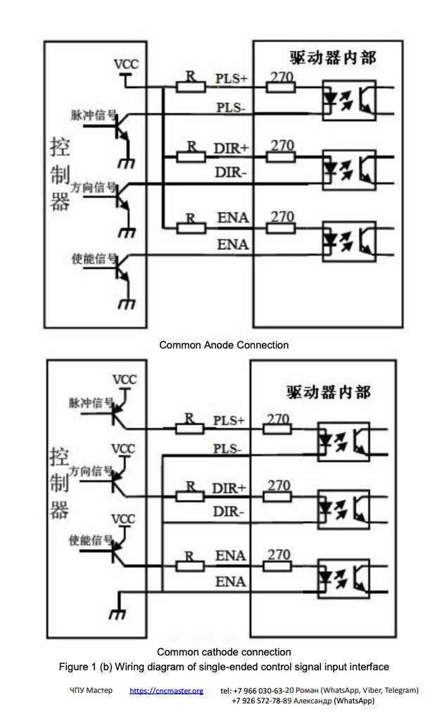
pulse+ and dir+ are connected to arduino's 5v
pulse- and dir- are connected to arduino's output pins
switch settings
I set it to 1600 pulses per revolution
sw7 is on because I didn't want to deal with enable signals
I am attaching the driver and motor links
I need to fix this by tomorrow or I might lose my job please help
Thanks for replying .When I do 3200, it doesnt rotate. This is why I reduced to 75. What do you mean by my driver handles acceleration I don't get it. What should I change this code for working
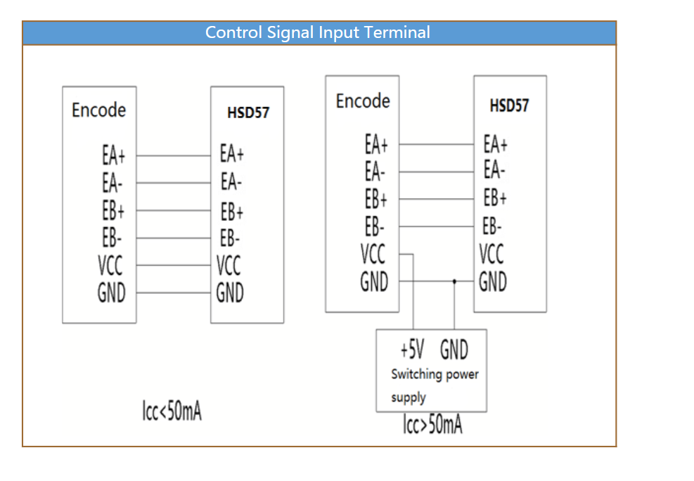
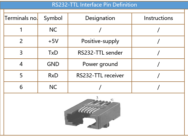
Thanks for replying. I try this one rn but my driver gave me red light seven times for one period. I looked at the Leadshine's datasheet and it says that means Position Following Error Protection. This is an closed loop driver. Do I have to cabled my Encoder cable to driver or RS233-TTL to my computer? I am so confused
Thanks for replying again. My driver has 6 input for encoder data's. However I can't get How should I supply 5v for encoder? Cause it has red an white cables for VCC and GND.
I did it but still same. If I don't misunderstood that the Closed Loop Driver doesn't work without encoder cable's. I don't understand the relation between ardunio which my code doesn't have any encoder value. How this driver read my encoder without any settings
Can you please post a copy of your circuit, a picture of a hand drawn circuit in jpg, png?
Hand drawn and photographed is perfectly acceptable.
Please include ALL hardware, power supplies, component names and pin labels.
Can you post some images of your project?
So we can see your component layout.
Do you have a DMM? (Digital MultiMeter)
As @bobcousins has pointed out, the Vcc and gnd terminals, check with DMM.
yes it is. If I just plug this in, will it be active immediately or do I need to make an additional setting? Also, does it feed 5v and ground from within itself?
Thanks for everyone comments, I just plug the encoder and motors run . You guys saved my job, really apprieciete it. Howver I have new problem. How will I see the encoder values from Ardunio, in my application, I need to send encoder data to another computer. All I see is the picture I sent. I have TTL cable, Should I cut the cable on one side and plug it into the Arduino on the other side?
I don't know that you can do that easily. I suppose that you could make a Y cable and interpret the encoded data on the Arduino.
I understand that the RS232-TTL can be used to configure the drive and perform some movements. There may be some software available to do that, and there may also be a specification somewhere of the commands you can send. I haven't seen a specification for either of those. You may be able to get them from your supplier or perhaps direct from the manufacturer.
Hi,
With a project my workplace designed last year, we had to do the same, read the encoder that was feeding back to the stepper driver.
We simply spliced into the encoder signals going into the driver, used a MOSFET to opto coupler for each encoder channel, only two channels were needed, and fed the opto output back to the PLC to count itself.
The driver's Vcc was able to power the opto input side of the circuit.