First of all, thank you jhaine , DrDiettrich , aarg dlloyd and TomGeorge for your replies, I can't express as someone trying to grasp the factors involved here how valuable it is to read your thoughts.
Apologies for not providing enough data @anon57585045 - as an amateur it's hard to gauge to what information to supply without padding out the question with superfluous data.
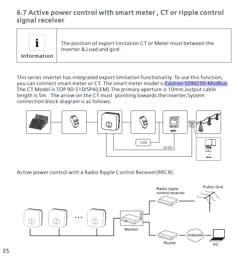
My goal is to digitally emulate the output of the TOP_90-S10_SP4 CT clamp so that I can arbitrarily control my 2x Growatt Inverter's power output to prevent exporting too much power back to my local grid, whilst allowing them to heat my water tank using a solar diverter prior to limiting the export function.
My lack of electronics knowledge in how to emulate the CT output is what brought me here. There seems to be a lot of posts around the Internet asking similar questions and none of them have come as close as this topic to actually answering the question.
My specific use case: I have 2 inverters and a solar power diverter that heats my hot water tank with excess energy. Because of the multiple inverters and the diverter, the traditional solution of plugging a CT clamp in to a single inverter (which is oriented to measure grid export) does not work. It just shuts down the inverter attached to the clamp and prevents the solar diverter from heating the water.
I already have ~real-time monitoring of all of the necessary data points feeding into a local MQTT server (export power for each inverter, solar diverter state, hot water tank state, grid export power etc). Using this data I have already built a (very rough but functional) software management interface that can calculate when, and by how much I need to limit the export for each inverter dynamically.
My solar installation includes 2 inverters, both are Growatt MIN 3600TL-XE - this is the most detailed data-sheet I could find. The CT clamp data-sheet is here.
My (very amateur) understanding of a CT-Clamp is that it outputs power at a ratio of the actual power flowing through the measured source. E.g if the source power is 90A at 240VAC the CT output would be 90mA (assuming a 1000:1 ratio). And because this is AC, that output mA will be in the form of a sine wave. However, I see that many CT clamps output power in the form of measurable DC voltage too, which would have been far easier to emulate.
If my understanding is correct (big if), my goal is to emulate that mA sine wave using an Arduino and feed it into my inverters CT Clamp port. In my particular case I will never require 90mA, the most I ever export is 7.2kW which, at 240v is 30A, so I need a 0-30mA output as a sine wave from an Arduino or ESP32.