This code does ping-pong a stepper motor between 2 end stops, the problem is, it doesn't register every time an end stop is activated and will just get stuck.
This becomes even more of an issue because I'd like to run the motor at high speeds as possible.
Im not sure what to test next, could it be an issue with the code or the mechanical endstops?
#include <Adafruit_MotorShield.h>
Adafruit_MotorShield AFMS = Adafruit_MotorShield();          //creating object
Adafruit_StepperMotor *secondMotor = AFMS.getStepper(200, 1);// Defin pins we are using the ports M1 and M2
 //-------------------------------------------------------INPUTS---------------------------------------------------------
int endStop1 = 2;     // Push button for left
int endStop2 =3;      // Push button for right

//Main Motor
int driverPUL = 7;    // PUL- pin
int driverDIR = 6;    // DIR- pin
int spd1 = A0;        // Potentiometer

//second motor
int spd2=A1;          //potentiometer
bool setdir2=5;       //direction switch for second motor


 //-------------------------------------------------------Variables---------------------------------------------------------

//Main Motor
int pd = 500;           // Pulse Delay period (speed)
boolean setdir1 = LOW;   // Set Direction

//second motor
int secondMotorSpeed;   //for the second motor after mapping
int x;                  //for the potentiometer values


// Interrupt Handler
//changes the direction of main motor and runs the second motor for 2 steps at the perviously set speed and direction.
void revmotor (){
  setdir1 = !setdir1;
  if(digitalRead(setdir2)==HIGH){
  secondMotor->step(2, FORWARD, DOUBLE);}
  else
  secondMotor->step(2, BACKWARD, DOUBLE);
}


void setup() {
  pinMode (endStop1, INPUT);
  pinMode (endStop2, INPUT);

  pinMode (spd1, INPUT);
  pinMode (driverPUL, OUTPUT);
  pinMode (driverDIR, OUTPUT);

  pinMode (spd2,INPUT);
  pinMode (setdir2,INPUT);

  attachInterrupt(digitalPinToInterrupt(endStop1), revmotor, FALLING);
  attachInterrupt(digitalPinToInterrupt(endStop2), revmotor, FALLING);
}


void loop() {
    x = analogRead(spd2);
    secondMotorSpeed = map(x ,0 ,1023 ,0 ,255);
    secondMotor->setSpeed(secondMotorSpeed);


    pd = map((analogRead(spd1)),0,1023,1000,50);
    digitalWrite(driverDIR,setdir1);
    digitalWrite(driverPUL,HIGH);
    delayMicroseconds(pd);
    digitalWrite(driverPUL,LOW);
    delayMicroseconds(pd);

}
Can you please post a copy of your circuit, in CAD or a picture of a hand drawn circuit in jpg, png?
Hand drawn and photographed is perfectly acceptable.
Please include ALL hardware, power supplies, component names and pin labels.
In particular, how you have wired your limit switches.
If you want the highest speed as possible, you should use the endstops for homing and travel measurement, and then use acceleration and deceleration to hit speeds above the self-start range.
Make sure your end stops are active by OPENING the switch, not by closing the switch. Add a condition to the interrupt code to NOT allow the interrupt to be processed unless some time has passed since the previous interrupt. You decide the time based on how fast your system operates.
Limit switches an present issues when used in motor applications.
All cables should preferably be shielded and not run alongside power runs.
There are a good few topics in the CNC section that cover this aspect in much more detail.
If running the motor in a small sketch consider adding some form of DEBOUNCE too.
Here is video showing issue, you can see sometimes it registers the endstop, other times takes many clicks to get it to change motor direction - Imgur: The magic of the Internet
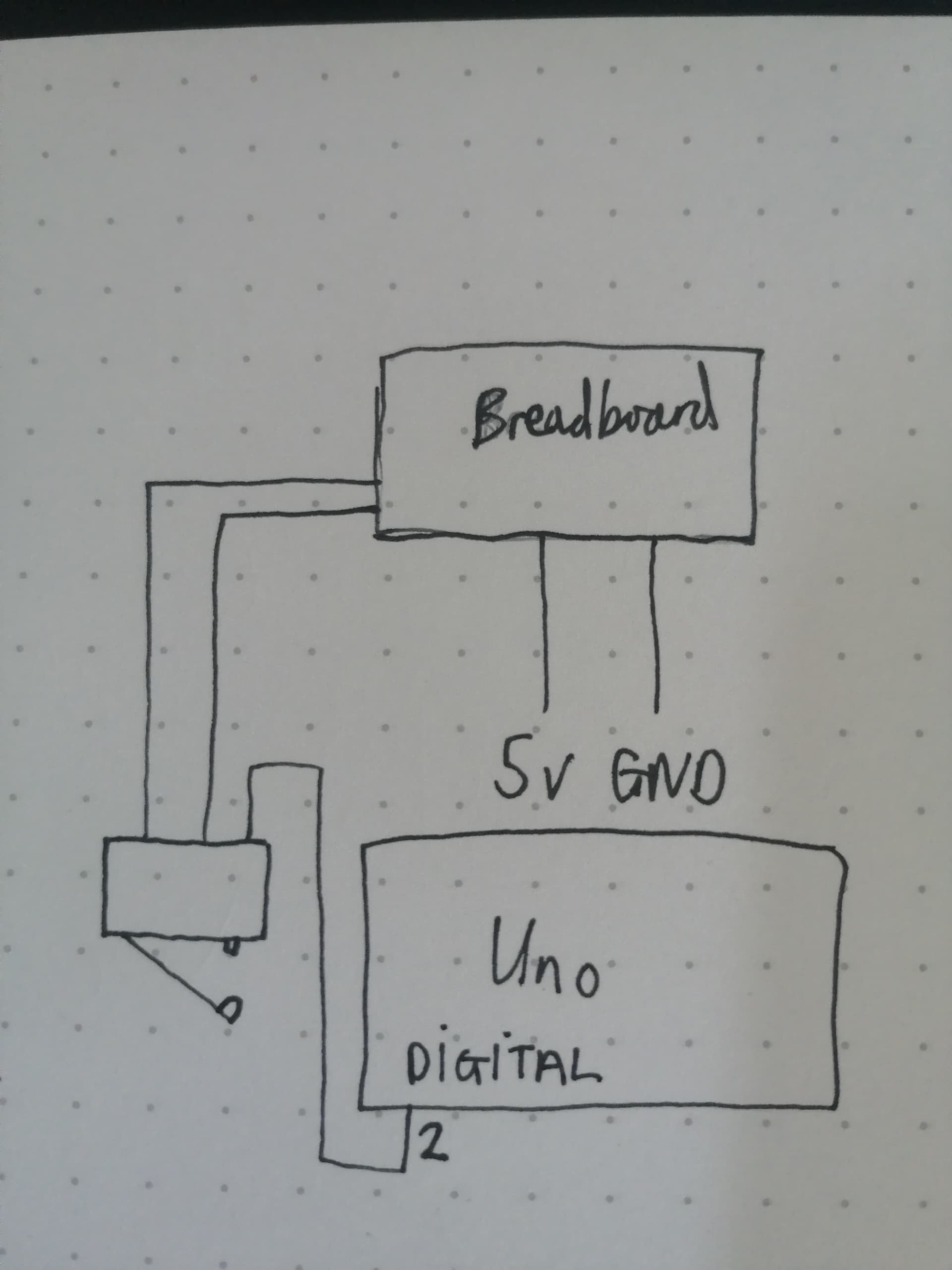
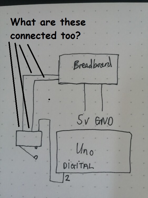
I just have the endstops powered through a breadboard and plugged directly into the digital ports on the uno
You are using all 3 contacts of the the microswitch. Does the UNO pin 2 ever go to float condition during switch transition? That may cause an undetermined condition (not high or low guaranteed) for the input.
Those switches already include some basic filters.
However as stated they need shielded cable and not the ones normally supplied.
You can still add additional filtering at the Arduino end too.
Most of mine have a ferrite core with at least two wraps through them.
Consider also adding an additional ground from the motor chassis to the Arduino.
Hi,
Can you place a DMM in DC volts and measure with respect to gnd the voltage on the digital input pins that are connected to the limit switches when you activate them.
Voltage when limit switch de-activated
Voltage when limit switch activated.
Can you please add pin names?