Error sending message with MCP2515

Hello guys,
I'm here having some problems with mcp2515 module with arduino uno.

I'm doing project which is control T motor with arduino using can bus communication.
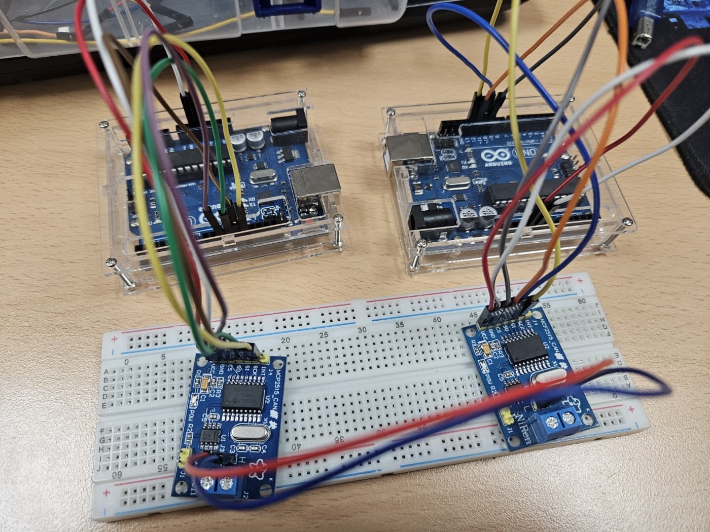
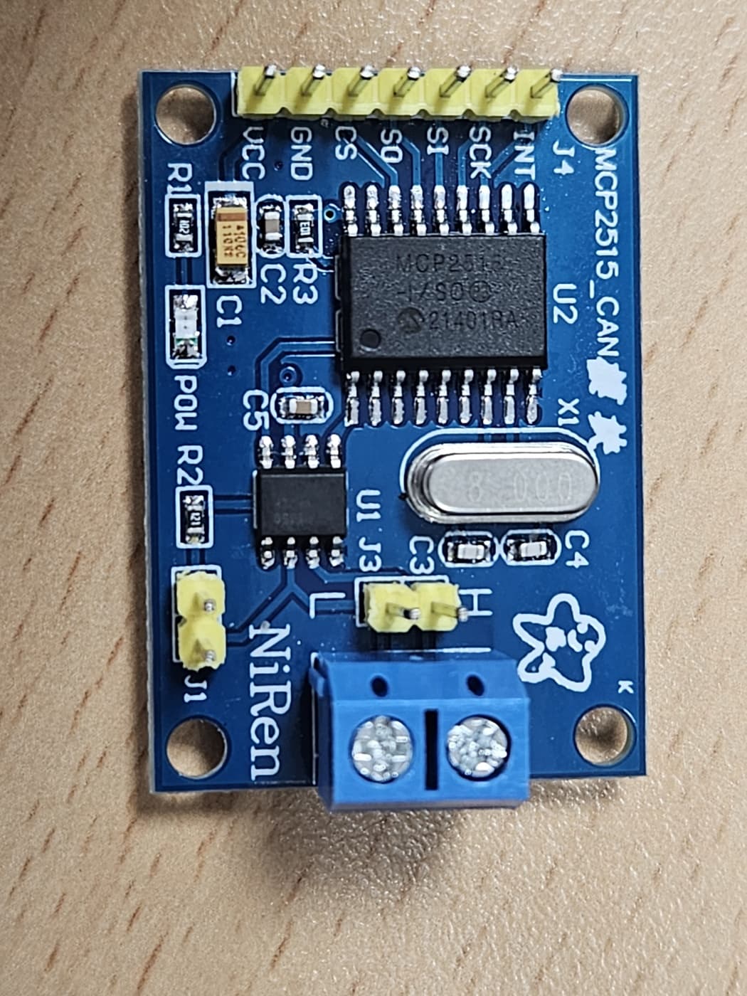
For hardware setup, I used arduino uno and mcp2515 moduel with 8MHz version.
Before connecting motor, I tried to connect 2 arduino uno with example of GitHub - coryjfowler/MCP_CAN_lib: MCP_CAN Library (can_send & can_receive).

When I run the example code, the can_send example output only "Error sending message..." and can't find the solutions......

Baudrate : 115200 | Using CAN_500KBPS |

// CAN Send Example
//

#include <mcp_can.h>
#include <SPI.h>

MCP_CAN CAN0(10);     // Set CS to pin 10

void setup()
{
  Serial.begin(115200);

  // Initialize MCP2515 running at 16MHz with a baudrate of 500kb/s and the masks and filters disabled.
  if(CAN0.begin(MCP_ANY, CAN_125KBPS, MCP_8MHZ) == CAN_OK) Serial.println("MCP2515 Initialized Successfully!");
  else Serial.println("Error Initializing MCP2515...");

  CAN0.setMode(MCP_NORMAL);   // Change to normal mode to allow messages to be transmitted
}

byte data[8] = {0x00, 0x01, 0x02, 0x03, 0x04, 0x05, 0x06, 0x07};

void loop()
{
  // send data:  ID = 0x100, Standard CAN Frame, Data length = 8 bytes, 'data' = array of data bytes to send
  byte sndStat = CAN0.sendMsgBuf(0x100, 0, 8, data);
  if(sndStat == CAN_OK){
    Serial.println("Message Sent Successfully!");
  } else {
    Serial.println("Error Sending Message...");
  }
  delay(1000);   // send data per 100ms
}

/*********************************************************************************************************
  END FILE
*********************************************************************************************************/
// CAN Receive Example
//

#include <mcp_can.h>
#include <SPI.h>

long unsigned int rxId;
unsigned char len = 0;
unsigned char rxBuf[8];
char msgString[128];                        // Array to store serial string

#define CAN0_INT 2                              // Set INT to pin 2
MCP_CAN CAN0(10);                               // Set CS to pin 10


void setup()
{
  Serial.begin(115200);
  
  // Initialize MCP2515 running at 16MHz with a baudrate of 500kb/s and the masks and filters disabled.
  if(CAN0.begin(MCP_ANY, CAN_125KBPS, MCP_8MHZ) == CAN_OK)
    Serial.println("MCP2515 Initialized Successfully!");
  else
    Serial.println("Error Initializing MCP2515...");
  
  CAN0.setMode(MCP_NORMAL);                     // Set operation mode to normal so the MCP2515 sends acks to received data.

  pinMode(CAN0_INT, INPUT);                            // Configuring pin for /INT input
  
  Serial.println("MCP2515 Library Receive Example...");
}

void loop()
{
  if(!digitalRead(CAN0_INT))                         // If CAN0_INT pin is low, read receive buffer
  {
    CAN0.readMsgBuf(&rxId, &len, rxBuf);      // Read data: len = data length, buf = data byte(s)
    
    if((rxId & 0x80000000) == 0x80000000)     // Determine if ID is standard (11 bits) or extended (29 bits)
      sprintf(msgString, "Extended ID: 0x%.8lX  DLC: %1d  Data:", (rxId & 0x1FFFFFFF), len);
    else
      sprintf(msgString, "Standard ID: 0x%.3lX       DLC: %1d  Data:", rxId, len);
  
    Serial.print(msgString);
  
    if((rxId & 0x40000000) == 0x40000000){    // Determine if message is a remote request frame.
      sprintf(msgString, " REMOTE REQUEST FRAME");
      Serial.print(msgString);
    } else {
      for(byte i = 0; i<len; i++){
        sprintf(msgString, " 0x%.2X", rxBuf[i]);
        Serial.print(msgString);
      }
    }
        
    Serial.println();
    delay(1000);
  }
}

/*********************************************************************************************************
  END FILE
*********************************************************************************************************/

Have you considered drawing a Schematic, your picture does not match your verbiage. Have you read the CAN specification? http://esd.cs.ucr.edu/webres/can20.pdf

At this point I would say it is doing exactly what it should, not transmitting a message. Did you read the information Gary Fowler put in his library and followed it? When you were born did you start out running or did you learn to walk first. Slow it down until you get it working, leaving the consol at 115,200 is best.

All of this is assuming it is properly wired.

Use at least a meter/yard of cable between the nodes if you can. You need to connect one transmit and one receiving unit. Even though it receives what it sends that is not available to the user but is part of the error checking. That is also part if the IFR (In Frame Response) of the protocol. Connecting wires between modules will not work, there is a thing called termination and a proper way of doing it.

Thank you for your reply.

Here is the schematic that you required. I connect each wire same as this.

I'm sorry but I really don't get what you are saying about "At this point I would say it is doing exactly what it should, not transmitting a message."

I also read the information that Folwer put in his library. But I still don't know....

That is actually a wiring diagram, not a schematic. Assuming you have wired it per the picture it should work. I have received several different MCP2515 modules over the years and they all did not have the same crystal. Try a slower baud, the slower the better until you get it working.

I mentioned a IFR (In Frame Response) that is an acknowledge sent by the slaves. As the master is sending the message there is a certin bit that is set to the recessive value and it monitors it for the duration of the clock cycle. One or more remotes have to drive that bit to the dominate state. If this does not happen the transmitter will assume an error and try again for whatever times it is set up for.

Have you connected anything else to these modules before trying CAN? Did you by chance connect a motor? Do you have access to a scope and or other modules? Do you have a multimeter and or a logic analyzer?

Can you post a picture of your setup?

Thank you for your reply.

Here is the picture of my setup

I didn't connect other devices with MCP2515 module I have. Just only for arduino UNO...

I replaced all the wires that connect between module and arduino, it still "Error sending message..."

I will guess from your answer that you had previously connected a motor to at least one of the UNOs. Try swapping the MPC2515 modules and check if the error changes. Also you do not have the termination jumpers (J1 on module) in place. You need them on the modules physically at the ends of the bus. You have two modules so both are at an end of the bus and need to be terminated.

Following your advice, I jumped the termination using cable and check the CAN H and CAN L has 120ohm through multimeters. (Check 60ohm between mcp2515 modules).

I changed the can bus modules and using same code above but didn't change at all....

I also check the sndStat that it printed (7) and (6).

byte sndStat = CAN0.sendMsgBuf(0x100, 0, 8, data);

It means "CAN_SENDMSGTIMEOUT" & "CAN_GETTXBFTIMEOUT" repectively.
Is there any way to solve these things?

P.S.
I did all the possible way to change or detach the cables or modules but it always same.

I am at a loss. I just put 8 CAN units together the past few days using the same module but a Nano in place of a UNO. Each and every one came up first try but I connected them to a known good bus that that has been operating for several years. The bus is at 250K 11 bit identifier. My modules are powered by an external power supply, have you tried that? Have you checked the voltages to be sure they are in spec.

Thank you for your reply...
I'm still trying to figure it out which is the problem...

Is there any possible way to reset mcp2515 in software?
If you know something, please let me know...

This is my mcp2515 module with 8MHz....

Also I double check that this module use 5V and arduino provide the power to the module.
(Just only connect 5V in uno and VCC in module)

This topic was automatically closed 180 days after the last reply. New replies are no longer allowed.