I have been able to compile and upload the "Blink / Hello World" test using pin 2 as and output to drive the LED. When I selected pin 15, the serial monitor produced pages of "stuff" without the "Hello world" being displayed.
According to the picture I have for this IC and board, pin 15 should be GPIO15.
Since this is my second attempt to understand the development board, I am probably doing something wrong. Please excuse an old man (83) for asking basic questions. Can some one point me in the correct direction?
Regards,
Wings
Please, post the picture of your Board.
Could you post your code?
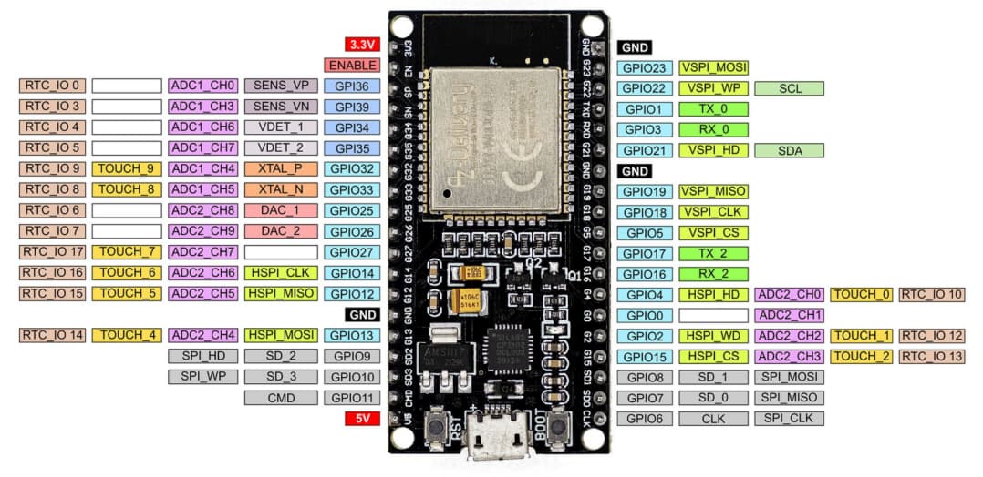
looking at esp32-pinout-reference-gpios it states
GPIO15 outputs PWM signal at boot, strapping pin
GPIO 15 (must be HIGH during boot)
could you be pulling it LOW at boot?
As requested:
Thanks for the reply.
//LED on GPIO2
int ledPin = 15;
void setup()
{
// put your setup code here, to run once:
//Set LED as Output
pinMode(ledPin, OUTPUT);
//Serial Monitor Setup
Serial.begin(115200);
}
void loop()
{
Serial.print("Hello");
digitalWrite(ledPin, HIGH);
delay(500);
Serial.println(" world!");
digitalWrite(ledPin, LOW);
delay(500);
I do not see a link to upload a picture. The device is an ESP 32-Wroom-32 board, if that helps.
Thanks
if load your code of post 5 into a ESP32-Wroom-32 it blinks LED on GPIO15 and prints
Hello world!
Hello world!
Hello world!
Hello world!
how have you wired the led? does it have a built in resistor?
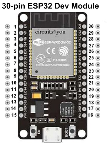
Search net giving the name of your Board like ESP32 Board. Then select a picture that matches with your Board, copy the picture, and paste it here in a post window. The Fig-1 is a pictorial view of a 30-pin ESP32; there are 36-pin version also.

My all three are of 30-pin version.
There are a LOT of restrictions on how and when you can use the ESP32 GPIOs. Many of them have fixed functions that CANNOT be disabled. Quite a few are used to connect the FLASH memory to the ESP module. Some can ONLY be inputs, others can ONLY be outputs. Several others MUST be held in a specific state (some HIGH, some LOW) during power-up, or the ESP will not function correctly. The Espressif WROOM-32 technical data sheet documents all of these many restrictions. There are only about a dozen, perhaps less, that are truly available for other purposes.

Yes I have the resistor. It works on GPIO 2 just not on GPIO 15.
wings


Perhaps there is a list that you could link to ?
Good link, good list.
Hello ![]() Everyone, I have been trying to develop an Iot of Esp32 Wroom32 30pin , but my sketch is all wrong errors are countless, I connect the data pin to pin 15 and what I get is errors, just wanted to develop an humidity and temperature reading iot for my school project which the presentation is on Wednesday 24the July. I need help, I also want to know how to use the message widget to give me a message when both temperature and humidity reading exceeds a particular threshold.
Everyone, I have been trying to develop an Iot of Esp32 Wroom32 30pin , but my sketch is all wrong errors are countless, I connect the data pin to pin 15 and what I get is errors, just wanted to develop an humidity and temperature reading iot for my school project which the presentation is on Wednesday 24the July. I need help, I also want to know how to use the message widget to give me a message when both temperature and humidity reading exceeds a particular threshold.