Are you saying have the esp8826 I/0 pin signal and activate a 1 amp ssr. The SSR activates a high amperage 120v relay?
Yes.
I'm not sure I completely understand. The fuse should be the weakest link. I only expect around 2-3 amps at most to be ever going through these boards. However, they are going to be connected to line voltage in the US which are protected by 15-20 amp breakers. I never expect the amperage to ever reach near this, but does the device HAVE to be capable of this if it is because it is on a line that is protected by the 15-20 amp breaker?
It makes sense to me that if a fuse is placed on the line voltage of my pcb, at an amperage less than all of the components on the board can handle, then the fuse will blow and protect the pcb if for some reason a high amp load was put on it or a short circuit occured.
For example, If my trace widths, components, etc all have the capability of handling 10A, and I place a 5 amp fuse on the line, If a load is placed on the device at say 8A, the fuse should blow well before any component or trace was damaged. What I am not sure of is if the fuse is considered enough of a safety net when a breaker is the second safety net and is rated higher than some of the components on the board.
I know that building inspectors in my area allow 15A switches be placed in a wall of homes that have 20A breakers covering them. I have never understood this, but it is allowed. I know that most residential switches will never see 15A from lights or receptacles, but if they did, it seems to me the 15A switch would be destroyed before the 20A breaker ever tripped. If however, there was an internal fuse inside the switch at 15A or less, this would seem to be protected.
Thanks for any input!
Use an SSR to trigger a 120VAC relay rated for your lamp load X 2, if lamps are incandescent, use an incandescent rated relay or contactor.
SSR module
You don't fuse for the supply current, you fuse for the current DEMAND. If your device, say, draws 4A under normal operating conditions, you would use ~5A fuse (possibly slo-blo if your device has high inrush current.) This gives your device 25% "headroom" no matter if the supply is 10, 15, or even 100A.
Do NOT rely on the line breaker to protect your device. The supply side has no knowledge of your device, only YOUR DEVICE knows what its limits are, fuse accordingly.
The breakers are in your mains supply to protect the WIRING of your home from melting and allowing the copper wires to contact and cause a fire. No other reason!
1 Like
So, I could safely use a pcb and components that were only designed to handle 1A on MAIN voltage as long as the pcb protects itself from over current and shorts?
Thanks!
Think of it as a 15A port (or pair of 15A ports on a duplex outlet) attached to a breaker-protected 20A wire. You could have several 15A ports where only sub-15A loads will physically plug into the 15A max sockets. A normal 15A duplex outlet would allow you to plug in 2 x 15A loads, and the outlet wouldn't fail. The 20A breaker protects the 20A wire from overload from loads drawn from the sum of the loads on all of the possible ports. Just like the 200A breaker protects the ~600A of circuit breakers in the my service panel.
In your case, you can put a 1A fuse in your device to protect its bits and outlets from exceeding your expected loads, you can physically plug it into either a 15A or 20A receptacle, and the wires behind the receptacle are protected by their breaker.
1 Like
Thanks. That makes sense. So typical 15a light switches in the wall are expecting there to be less than 15A at all times.
I guess my next question, as I am working on the pcb design, is what is the best transistor/optocoupler to use to receive the signal from the wemos esp8826 board and amplify (for lack of a better word) to send to the songle relay I plan to use? I have used a tip120 for a different application, but I’m not sure it is the best. I have read about using a 2n2222 transistor? I really don’t know what I would need to have an optocoupler do it? I assume the optocoupler would help isolate the microcontroller better from the main voltage than a transistor would?
Thanks all!
More than 15 amps of lighting would be more than 1800W of light. If you are designing the lighting circuit for more, you'd need a beefier switch and beefier wires. The 15A plugs are a promise that they don't/won't take more than 15A, so the receptacles can expect it to draw less than 15A.
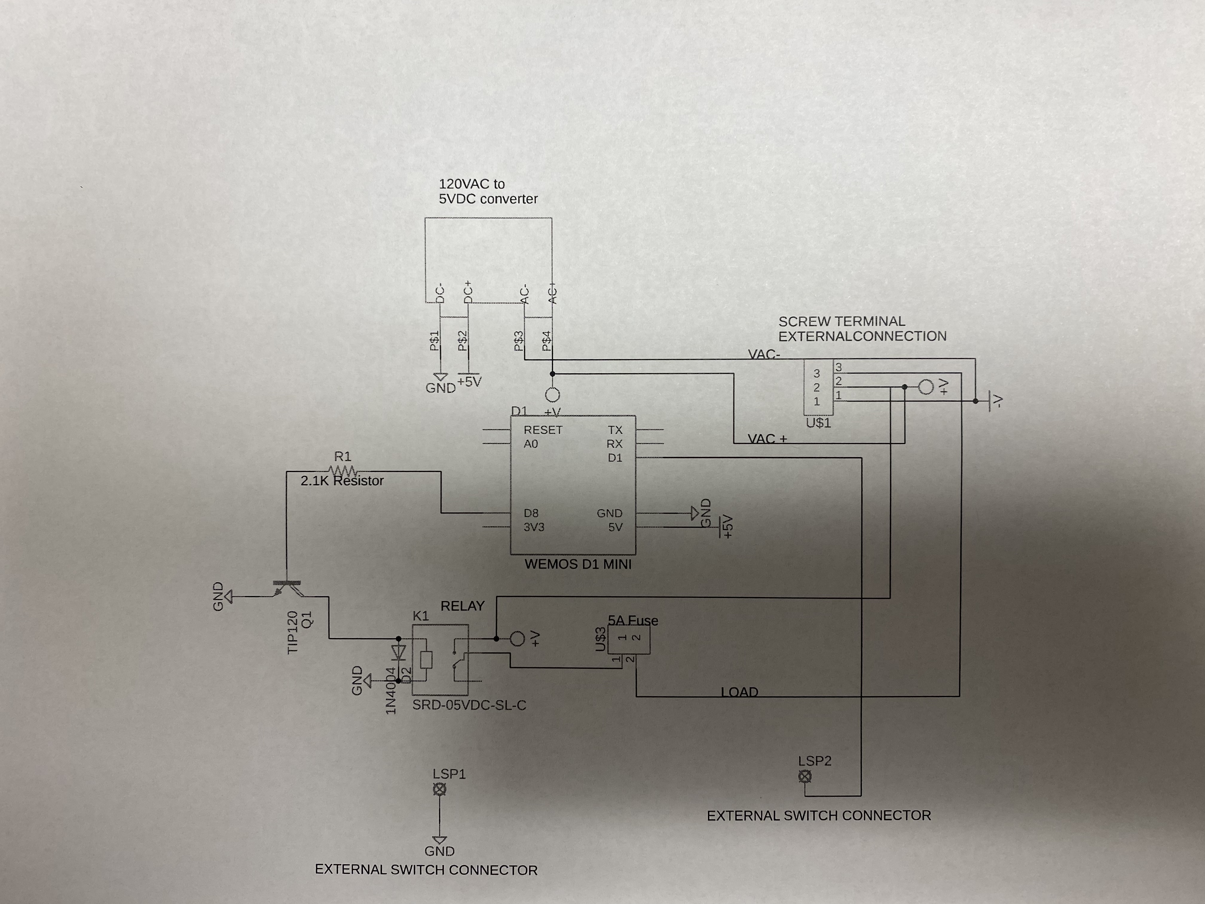
Ok, I have a little closer diagram of what I am trying to do. I am looking for advice/criticism. @LarryD I am going to be making a pcb again and hoping you will correct all my mistakes as you did in my previous pcb!
Again this is what I am doing: I am using a wemos d1 mini, a 120VAC to 5VDC supply board, I am planning to have the wemos board send a digital signal to a transistor (TIP120 at this point but open to advice), The TIP120 (or whichever transistor/mosfet/optocoupler is best) will activate a songle srd-03vdc-sl-c 10a relay (could use a srd-05vdc-sl-c 10a if needed) . The relay will control a 120VAC load that I anticipate being less than 5A. The coil resistance on the 3v relay is 20-25 ohms at 120-150mA and the 5v relay the coil resistance is 70-80 ohms with 71-89mA. I have read many threads on doing this calculations (even one that I started and had great answers), but I can't figure out the best way to determine which transistor/resistor combination to use. I know the tip120 will work because I have tried it and I have them readily available, this is why I chose it. In my schematic and the one that I tried, I used a 2.1k resistor/tip120 combination.
I also have included a 1N4004 diode across the coil of the relay. I know that I need this flyback diode, but not exactly sure how to choose the right one.
I have a fuse inline of the load set at 5A. I would like to be very conservative with my fuse. I do have it set in the AC- side which I don't know why this would not work.
Here is my schematic at this point:
Thanks!
Suggest you draw your schematic in a more standard way, lots of example on the WEB.
A TIP120 is over kill.
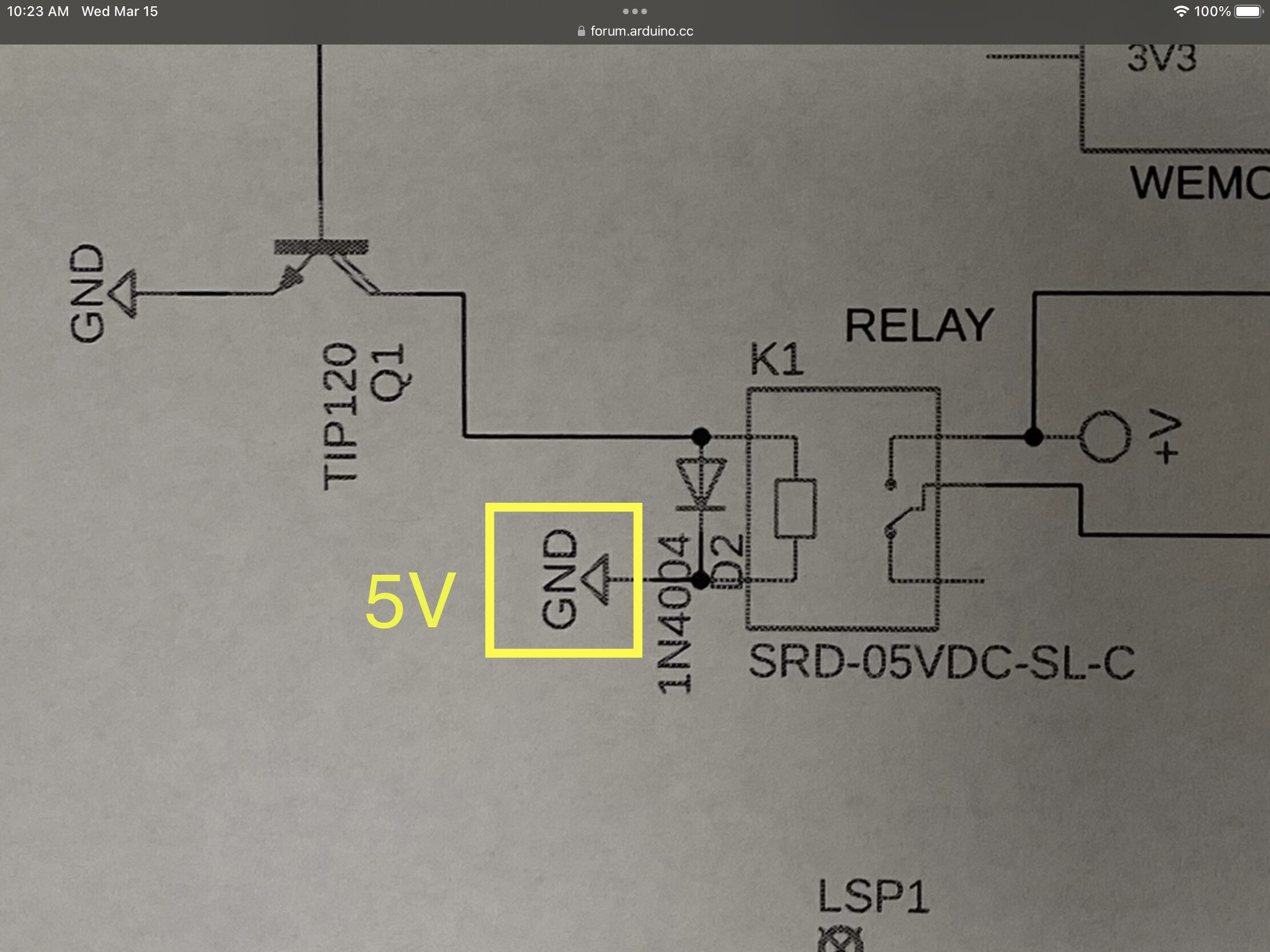
This is the schematic that is coming from fusion/eagle. Are you saying that should be 5v instead of GND?
Thanks!
Yes
Ah Ok, I missed the GND/5v mix up. I will fix that. Is it bad to use the tip120s since they are overkill? What will it hurt? What is better?
Thanks!
The TIP120 has a saturation voltage which is quite high. > 1.2V
Essentially it steals this from the relay.
Better to select regular NPN BJT where the saturation is around ~.3V
Suggest you place the fuse in the V+ line.
Just an aside:
Schematics are generally laid out to "read" left to right signal flow. (inputs left, outputs right). Then individual components arrainged by voltage. Highest voltage at the top of page, lowest at bottom. This is the "natural" layout. Try to arrainge accordingly. The "ground on both sides" error would be much more noticable. As would voltage mixing errors (a high voltage lead wandering around in low voltage areas.) The electrical separation becomes physical separation and drawing visual separation -- all must be maintained, especially when mains voltages/currents are expected
Looking for one now. You chose the .3V because it is 1/10th the incoming voltage of the wemos (3.3v)?
Curious as to why?
AH, makes sense. I will try to adjust accordingly.
Thanks!
Fuse so an external overload doesn't fry your traces.
Often the readily available 2N2222 transistor is adequate.
The pick current of those relays is quite low.
What is the resistance of the relay coil ?
We usually add a fuse as close to the source as possibly so the complete external wiring is protected.
This would mean, place the fuse where the V+ comes on to the PCB.
The circuit flow is usually left to right, top to bottom, plus voltages at the top of the schematic.