Suspected EMI issues. AC relays

I am looking to control 18 latching relays from an Arduino Mega. The relays will control a series of 240V AC lights.
I have tried to do my own research, due diligence and follow best practices.

The problem: when I am turning the lights on and off, the board will appear to be 'hung', eventually the watchdog timer will reboot the board and it comes back on line and I can control it again. This only happens when there is AC load through the relays.

I have designed two PCBs, one a board with ULN2803s on, and a second board with the relays on.
I finally got round to wiring it up this weekend, and the code works well, the relays all work as intended UNTIL I turn the AC load on.
The relays are 12V coils, I power the Arduino with a 12v barrel jack, and take the 12V to power the coils from the VIN pin.
I use the flyback diode on the ULN2803 to minimise kickback voltages from the relay coils. I had hoped this was enough. And it seems to be. The code runs flawlessly when the relays are controlled but there is no 240V AC going through them. I can turn the relays on and off to my hearts content, and the board doesn't 'hang'.

As soon as I have the AC power going through the load, a couple of flicks of the relays will cause the hang up.

This leads me to suspect that I am getting EMI rather than bad code or issues with the kickback from the relay coils.

The Arduino code is:

#include <Ethernet.h>
#include <PubSubClient.h>
#include <avr/wdt.h>
#include <string.h>

// MAC Address
byte mac[] = {
  0x00, 0xAA, 0xBB, 0xCC, 0xDE, 0x10
};
IPAddress ip(192, 168, 1, 8);

const int boardno = "One";                                          //Change this for each board

const char* mqtt_server = "192.168.1.3";                            //MQTT Server IP Address
const char* clientID = "Relays";                                       //Arduino ID
const char* willTopic = "House/Availability/Relays/One";             //Will Topic
const char* willMessage = "offline";                                  //Disconnected Message
const char* MQTTUser = "XXXXX";                                       //MQTT User
const char* MQTTPass = "XXXXXXXXXXXX";                        //MQTT Pass

const char board[19][50] = {
  "Porch/Lights/Relays/One", "Hall/Lights/Relays/One", "Office/Lights/Relays/One",
  "Lounge/Lights/Relays/One", "Lounge/Lights/Relays/Two", "Kitchen/Lights/Relays/One",
  "Kitchen/Lights/Relays/Two", "DiningRoom/Lights/Relays/One", "Utility/Lights/Relays/One",
  "BathroomOne/Lights/Relays/One", "Garage/Lights/Relays/One", "BackDoor/Lights/Relays/One",
  "Shed/Lights/Relays/One", "GarageLoft/Lights/Relays/One", "BedroomOne/Lights/Relays/One",
  "BedroomTwo/Lights/Relays/One", "BedroomThree/Lights/Relays/One", "BedroomFour/Lights/Relays/One"
};

//Initialise relay pins
int pins[36];                                                         //vairable to store each pin
int nextpin;

int willQoS = 2;                                                      //Will QoS
boolean willRetain = true;                                           //Will Retain
int counter = 0;                                                      //Used to reconnect MQTT server
EthernetClient ethClient;                                             //Ethernet Client
PubSubClient client(mqtt_server, 1883, ethClient);                    //MQTT Client

void setup() {
  wdt_enable(WDTO_8S);                                                //Set up watchdog with 8s timeout
  for (int i = 0; i < 36; i++) {                                      //Assign 2 pins per relay starting from 2
    pins[i] = i + 2;
    if (i >= 10) {                                                    //Skip pin 10
      pins[i]++;
    }
    if (i >= 21) {                                                    //Skip pin 21
      pins[i]++;
    }
    pinMode(pins[i], OUTPUT);
  }
  /*
    Serial.begin(9600);
    while (!Serial) {
      ;                                                                 // wait for serial port to connect
    }
  */
  Ethernet.begin(mac, ip);
  delay(2000);                                                        // Allow the hardware to sort itself out
  if (client.connect(clientID, MQTTUser, MQTTPass, willTopic, willQoS, willRetain, willMessage, true)) {  // Connecting to MQTT Broker
    //Serial.print(clientID);
    //Serial.println(" connected");
    client.subscribe("House/RelayBoards/One/+/+/Relays/+");                    //Subscribe to topic
  }
  /*
    else {
      Serial.print(clientID);
      Serial.println(" connection to MQTT Broker failed...");
    }
  */
  client.publish(willTopic, "online", true);                              //Publish Online to MQTT
  for (int i = 0; i < 18; i++) {                                                       //Publish relays controlled by this board
    char topicbuild[35] = "House/RelayBoards/One/Layout/";
    char cstr[20];
    itoa(i, cstr, 10);                                                                     //Turn the number of the relay into words
    strcat(topicbuild, cstr);                                                       //Build the new topic
    client.publish(topicbuild, board[i], true);
  }
  client.setCallback(callback);                                           // Setup callback
}


// Reset Function delcared
void(* resetFunc) (void) = 0;


void loop() {
  Ethernet.maintain();
  if (!client.connected()) {                                              // Reconnecting to MQTT server if connection is lost
    //  Serial.println("MQTT dropped");
    reconnect();
  }
  client.loop();                                                          //set up subcribing loop
  delay(50);
  wdt_reset();                                                              //Reset watchdog
}

//Keep trying to reconnect
void reconnect() {
  while (!client.connected()) {
    //Serial.print("...");
    if (client.connect(clientID, MQTTUser, MQTTPass, willTopic, willQoS, willRetain, willMessage, true)) {
      client.publish(willTopic, "online", true);                          // Publish Online
      //  Serial.println("Connected");
      for (int i = 0; i < 18; i++) {
        char topicbuild[35] = "House/RelayBoards/One/Layout/";
        char cstr[20];
        itoa(i, cstr, 10);
        strcat(topicbuild, cstr);
        client.publish(topicbuild, board[i], true);
      }
      client.subscribe("House/RelayBoards/One/+/+/Relays/+");                    //Subscribe to topic
      counter = 0;
    }
    else {
      //Serial.println(counter);
      ++counter;
      if (counter > 5) resetFunc();                                     // reset board after 5 minutes of trying
      delay(5000);
      wdt_reset();
    }
  }
}


void callback(char* topic, byte * payload, unsigned int length) {       // subscribe function for relay control
  char message[length + 1];

  // convert the payload from a byte array to a char array
  memcpy(message, payload, length);

  // add NULL terminator to message, making it a correct c-string
  message[length] = '\0';

  //Presevere topic
  char topicOG[50];
  strcpy(topicOG, topic);

  char *strtokIndx; //Will be used as an index
  const char s[2] = "/"; //The seperator
  char newTopic[50] = "\0";
  strtokIndx = strtok(topic, s); //Will be House
  strtokIndx = strtok(NULL, s); //Will be relay boards
  strtokIndx = strtok(NULL, s); //Get board number
  strtokIndx = strtok(NULL, s); //Get room
  strcat(newTopic, strtokIndx);  //Add room to topic
  strcat(newTopic, s);          //Add seperator
  strtokIndx = strtok(NULL, s); //Get what
  strcat(newTopic, strtokIndx);  //Add what to topic
  strcat(newTopic, s);           //Add seperator
  strtokIndx = strtok(NULL, s); //Will be Reays
  strcat(newTopic, strtokIndx);  //Add Relays to topic
  strcat(newTopic, s);           //Add seperator
  strtokIndx = strtok(NULL, s); //Get num
  strcat(newTopic, strtokIndx);   //Add num to topic

  int check;
  int mCheck;
  const char *cmp = "ON";
  char *state;
  int whichpin;                   //Vairable for which pin needed
  for (int i = 0; i < 18; i++) {  //Step trhough each relay
    check = strcmp(board[i], newTopic); //Topic found?
    if (!check) {                     //Yes
      mCheck = strcmp(message, cmp);
      if (!mCheck) {     //Turning it on?
        whichpin = pins[2 * i + 1];         //Pick pin for on
        state = "On";
        //Serial.print(i);
        //Serial.println(" ON");
        //Serial.println(whichpin);
      }
      else {                            //Turning off?
        whichpin = pins[2 * i];     //Pick pin for off
        state = "Off";
        //Serial.print(i);
        //Serial.println(" OFF");
        //Serial.println(whichpin);
      }
      break;                            //Don't need to keep looking
    }
  }
  digitalWrite(whichpin, HIGH);         //Turn relay pin on
  char topicStat[50] = "House/";
  strcat(topicStat, newTopic);          //Build topic for state publush
  client.publish(topicStat, message, true); // publish
  strcat(topicOG, s);                   //Add separator
  strcat(topicOG, state);             //Build topic for 2nd state publish
  delay(100);                            //Delay >50ms for relay to switch
  digitalWrite(whichpin, LOW);         //Turn relay pin on
  client.publish(topicOG, "OFF", true); // publish
}

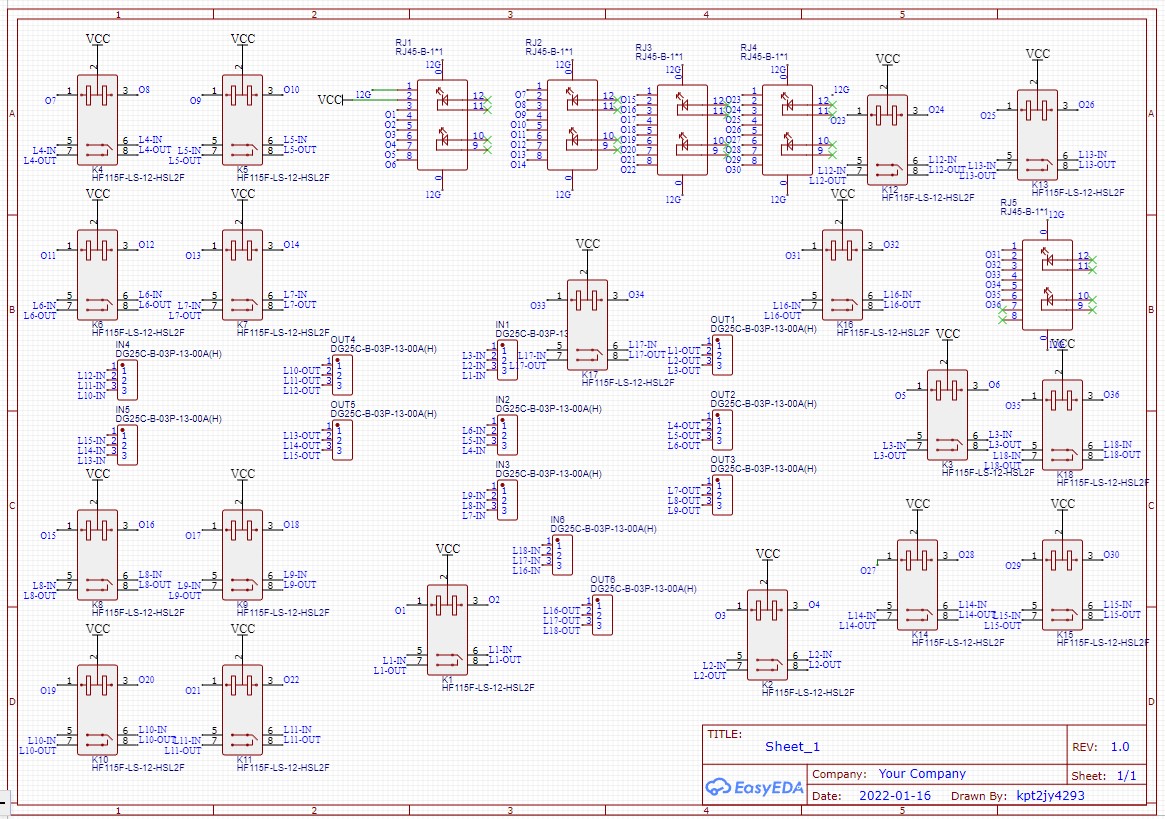
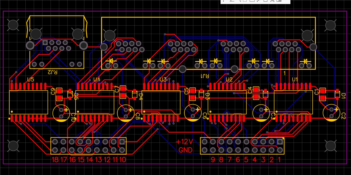
I will also attach pictures of the PCB boards and both their schematics.

The Arduino is mounted and connected via jumper wires to the ULN2803 board.
The ULN2803 board is connect via 5 ethernet cables to the relay board.

The relay board schematic looks a bit overwhelming, but essentially each latching relay has a COM and two 12V inputs on the coil side. There is nothing on the relay board except for the relays, 5 ethernet ports and screw terminals for the AC loads.

The relay board has 18 relays, which means there are 36 outputs from the Arduino.

This leads to 5 ULN2803s, each 2803 has a 100nf ceramic capacitor, a 10uf aluminium electrolytic capacitor and a Zener diode. All of these are positioned next to the power pins of 2803s. This was done based on advice I read online to help protect the 2803s form the kickback.
I also have utilised the built in flywheel diode on pin 10 of the 2803s.

The wires between the Arduino are neat and well organised. The 5 ethernet cables going to the relay board are straight and neat.

The crux of the question how do I go about reducing the (suspected) EMI I am getting when the AC power is on?


I see several things. The com pin (10) from the ULN goes to the + of the capacitor but no where else. It is a very fast rising signal and the 10uF cap will not see it. It needs to connect to the + of the relays. Also realize any wires connecting various components are antennas and can coupole noise to the Arduino. You can try using shielded wire or twisted wire with the ground connected at only one end.

Thank you - a little confused as to the pin 10 comment? Pin 10 is connected to both capacitors and the zener diode (for each 2803), as well as then off to the +ve side of the Relays via the ethernet cable?

The ethernet cable is already twisted wire - I could try shielded ethernet, which help? But is that enough to stop the random hangs?

This is a classic case of EMI induced by switching the power, this is almost inevitable.

The cure is to fit a snubber onto each relay contacts circuit. This is simply a resistor and capacitor. However the capacitor has to be none polarised and have a working voltage higher than the peak to peak voltage of the AC, not just the RMS voltage.

Look here to find what it is all about

1 Like

This was what I suspected - now to ask the dumb questions:

This snubber needs to be on the relay coil contacts? So each latching relay would need two snubber circuits?
Or is this a snubber on the AC side of the relays?

Look at the diagram, it goes across the relay contacts. So only one per relay.

Thank you - would rather ask just so I didn't assume the wrong thing!

Reading about snubber circuits, I have found stuff about MOVs too they seem to do subtly different jobs, is that something you'd recommend?

Likewise I have seen snubber circuits in parallel with the load as well as in series across the relay contacts. Any pros/cons with either design?

Showing my lack of in depth understanding - if I have the RC snubber across the relay contacts, would that still allow current to flow to the lights?
IE given it is 240V AC current to the lights if the relay was open, would it be 'safe' to work on the lights given than the RC snubber bridges the relay contacts?
In all reality I would turn the power off at the fuse board, but just trying to understanding exactly what the snubber circuit gives me

No a MOV is for over voltage protection, this is not what you want.

It gives you a slowing down of the rate of current rise in the circuit, this is known as the di / dt ( delta current by delta time). It is the sharp change in current in a short amount of time that generates the electromagnetic interference that is causing the reset problems. So the slower the rise the less interference you generate.

Yes there would be some current flowing but totally insignificant due to the component values used.

I have only seen ones across the contacts.

1 Like

Okay all makes sense - And for 240V AC current powering LED bulbs, what value R and C would you recommend?
Thank you for your help so far!

Edit:

And does distance of the RC snubber make a difference IE - does it need to be over the relay contacts themselves, or could I put it over the screw terminals for the load?

It depends on the current draw, are they incandescent or LED? What is the power rating of the bulbs?
We had a problem recently that was solved by using a snubber:-
Interferance from switching relays

Yes, as close to the contacts as possible.

It should go directly to the solenoid +, the capacitor is doing nothing. This will quench the flyback voltage from the solenoid. You need to get rid of the flyback spike, that generates a lot of EMI.

It depends on the current draw, are they incandescent or LED? What is the power rating of the bulbs?

They will be LED GU10s for the most part ~5Ws each. No more than 10 per circuit.

We had a problem recently that was solved by using a snubber:-
Interferance from switching relays

Interesting - I will read through that.

And start thinking if I can retrofit the RC snubber or if it will mean new boards.

It should go directly to the solenoid +, the capacitor is doing nothing. This will quench the flyback voltage from the solenoid. You need to get rid of the flyback spike, that generates a lot of EMI.

Apologies, I am probably being dense - but it does go directly to the relay +?
Example wiring

That is an example of how it is wired, except the relay is on a separate PCB joined via ethernet cable.
The advice for the two capacitors and the Zener was taken from this thread:
https://www.edaboard.com/threads/uln2803-with-led-with-12v-vcc.371075/

So that means you don't need to bother with any other diodes across the coil like @gilshultz was suggesting.

As you say the problem only appears once you attach the mains. If it were interference cause by the relay coil then it would still be there before you connect the mains. The fact that it is not shows that this is not the problem area.

Okay so I read the thread you previously linked, some good information in there. The snubber design calculator is probably beyond my knowledge.
Would something like this Snubber be suitable?
I could add one of those across each relay if that will fix the problem.
Or happy to design one myself if you can point me in the right direction for the values/components.

I am also beginning to think I may have a memory issue with the code - I have been running the Arduino for a couple of days (with no AC power connected) and occasionally just trigger the relays to check it is still running.
I noticed last night that every couple of hours the board appeared to reset (the MQTT LWT showed it briefly went offline)

In the instance I had, (the thread that Grumpy Mike referred to) I was only having issues when I had a load through the relay. Activating the relay and turning on the solenoid didn't seem to be an issue, it was only when relays and the solenoid were shut down. I could turn relays on and off no problem without loads being drawn or loads shut down. I also did in my instance, put the snubber on the load side and not across the relay. The biggest reason I wanted to try across the load is because the solenoids would only be energized about 1 to 2 percent out of the year.

By the sounds of your last post, you may have some coding issues that could be a problem.

I had my setup going for almost a couple years with occasional restarts.
My first thought was code issues in my case.
Then not long ago, I reworked all of the coding sections related to where I could be having a problem. Problem solved..... well not quite.
After more testing and for making it impossible to be a coding issue, I came across the EMI thought.
With my lack of knowledge of EMI, I probably would have gotten to that being the issue early.

Maybe in your case with your last post, you could do testing in stages:
-running code with no relays connected
-running code with relays connected but no AC loads drawn
-then finally running with drawing AC loads

The coil wires can and sometimes do act as antennas, and can pick up some transient voltage from the load as the contacts change state generally when they open. These transients would be radiated, not conducted. Your problem is not an easy one.

Yes I think I'd agree. I definitely do have an issue when the AC load is on. As soon as there is AC load I can only turn a relay on or off a couple of times before the board resets.
With the relays connected but the AC power off, I can flick the relays as much as I like and it doesn't crash BUT I have been seen the occasional reset randomly (not caused by turning a relay on or off) - for example last night it ran for 6 hours after I went to bed, then reset 3 times in the space of an hour.
I can only assume this is a coding issue.
SO I think I have two problems to fix.

EDIT:

I think I may have found my coding issue - some of the MQTT topics I was building exceed the char space I had given.
I have given those strings extra length to stop the overflow so hopefully that I will stop the random crashes.
I will report back - in the mean time I can start designing a snubber if anyone can steer me to the correctly sized R & C values
At the moment these relays only control light circuits, but would the RC values change if it was wired to an extractor fan? A fridge? Etc

That would cause you problems because you would be writing over some other variables in your code.

The optimum values would change. But you are always better off with a snubber than without one, even if it did not have the best values you can use. It is slowing down the current rise time that is important.

Okay the pre built snubbers have arrived - I will fit them to the relays this weekend. Still getting the sporadic hangs (or at least appearance of a hang - the LWT is published before it resets). Trying to chase down what is causing this still. I wondered if it could the use of delay()?