ESP32 Button Library -- Using Multiple Button s

I am trying to adapt the ESP32 Button Libray example sketch for a single button press to use for multiple buttons and am having difficulty coding the serial print output for each button.
In the code attached I need to modify this call-back statement to produce a separate output for each button press, but at present whichever button I press generates the same print out.
Can anyone please point me in right direction?

static void onButtonPressDownCb(void *btn, void *usr_data) {
 
  Serial.println("Button 1 pressed"); 
}

FULL CODE BELOW


#include <Arduino.h>
#include "Button.h"


static void onButtonPressDownCb(void *btn, void *usr_data) {

  Serial.println("Button 1 pressed");
}


void setup() {
  // put your setup code here, to run once:
  Serial.begin(115200);

  Button *btn1 = new Button(GPIO_NUM_4, false);
  Button *btn2 = new Button(GPIO_NUM_5, false);
  Button *btn3 = new Button(GPIO_NUM_12, false);
  Button *btn4 = new Button(GPIO_NUM_13, false);
  Button *btn5 = new Button(GPIO_NUM_14, false);
  Button *btn6 = new Button(GPIO_NUM_15, false);
  Button *btn7 = new Button(GPIO_NUM_32, false);
  Button *btn8 = new Button(GPIO_NUM_18, false);
  Button *btn9 = new Button(GPIO_NUM_19, false);
  Button *btn10 = new Button(GPIO_NUM_33, false);
  btn1->attachPressDownEventCb(&onButtonPressDownCb, NULL);
  btn2->attachPressDownEventCb(&onButtonPressDownCb, NULL);
  btn3->attachPressDownEventCb(&onButtonPressDownCb, NULL);
  btn4->attachPressDownEventCb(&onButtonPressDownCb, NULL);
  btn5->attachPressDownEventCb(&onButtonPressDownCb, NULL);
  btn6->attachPressDownEventCb(&onButtonPressDownCb, NULL);
  btn7->attachPressDownEventCb(&onButtonPressDownCb, NULL);
  btn8->attachPressDownEventCb(&onButtonPressDownCb, NULL);
  btn9->attachPressDownEventCb(&onButtonPressDownCb, NULL);
  btn10->attachPressDownEventCb(&onButtonPressDownCb, NULL);
}

I’d guess that each button needs a separate function specified in the attach calls in setup.

I'd say.

Following the pattern, here untested is what we mean

static void onButtonPressDownCb1(void *btn, void *usr_data) {
 
  Serial.println("Button 1 pressed"); 
}


static void onButtonPressDownCb2(void *btn, void *usr_data) {
 
  Serial.println("Button 2 pressed"); 
}

Once you feel the pain of copy/paste/editing your way through this, you'll want to take time off pursuit of the goal and learn about array variables, loops and functions.

You code will be about 1/Nth the size, easier to write, perfect, modify and enhance.

a7

Yes I think so, but cant work out the syntax to connect each callback with the
attachPressDownEvents I've allocated to each button.
Im guessing that there is a Button_Handler which needs to be defined for each button but there's nothing in the documentation which helps.

Here is where the callback function is associated with the button:

  btn2->attachPressDownEventCb(&onButtonPressDownCb, NULL);

you assigned the same callback function to every button, it is entirely correct and logical that every button is using the same function.

a7

Id love to be able to use arrays for this but am a novice !

Where should I start to reduce this code?

Any time new things are created by appending a digit or otherwise modifying an existing name, you can think about array variables.

Any time you copy/paste/edit a block of code to make code to handle an additional <whatever>, you should think about using a function.

With this particular sketch, the array variables get a litte ltricky; I am reluctant to offer an example whilst sitting in the transport cafe looking through the little window. I can't test anything, and to offer an untested and very too likely flawed sketch would be a step in the wrong direction.

For now, google and read

 arduino array variables

and

 arduino functions

to start at the beginning by exposure to their use in simpler circumstances. Trust that the same concepts will be useful here in your real project.

When I am next the lab I'll take a stab at a direction you might take with the current sketch.

a7

That would be great if you can spare the time. :+1:

I have no life, so don't worry about that.

Just now I cannot find the library you are using, so if you could provide a link to it please do.

And I am wondering what the ultimate purpose of having multiple buttons is. I understand you are just trying to work what you were exposed to in some examples code (to which it would also be good to be pointed, or post the example code unchanged right here).

But using that callback mechanism may not be a very good match - choosing a button library and which of its ways to know about button activity to use is dependent on what you are doing with all those buttons.

Without being able to see, I cannot know if the library you are using has other better ways more suited to your circumstances.

So for now I ask you to say more about what this is ever going to do with the buttons, unless you are just experimenting. My experiments are usually informed by whatever project I am working on, unless it's "learning time" I make for myself where I am not worried about a servo operated cat feeder or whatever.

a7

Thanks
The library i'm using is
image
which I found in my Arduino IDE library list.
The project is a real life application and I started working on it during covid, gave up and recently picked it up again.

For my project the "Buttons" are room presence sensors, which have a normally open relay output.

Walk in the room, sensor activates, relay closes and stays closed for as long as its activated and goes off around ten minutes after leaving the room. Like a single long press button which gets pressed once and doesn't matter what happens when button is released?

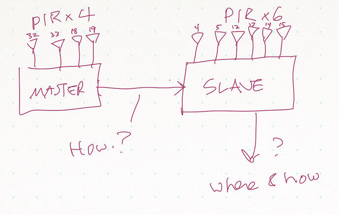
The added complication is that these PIR presence sensors are ten in number and are located in two parts of the building, 4 in one place and 6 in another.

So I'm using 2 ESP32s which communicate using ESPNOW , and the hardware is quite straight forward.
The Master has 4 inputs

GPIO PINS 32 33 18 19 each to GND when switched by room occupancy sensor
and the Slave has 6.

GPIO PINS 4 5 12 13 14 15 to GND when switched by room occupancy sensor

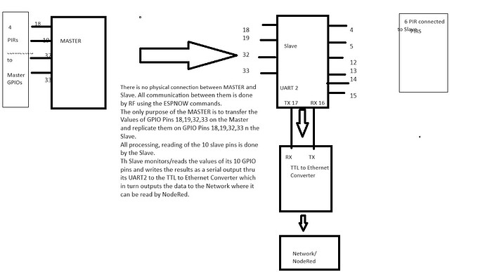
All activations are collected by the Slave which uses serial2.println to send the relevent string to my network using the UART 2 of the slave via a Waveshare UART TTL to ETHERNET converter.

GPIO PIN 16 (RX) to TX on Waveshare Uart to Ethernet module
GPIO PIN 17 (TX) to RX on Waveshare Uart to Ethernet module

2-Channel UART to Ethernet Converter (CH9121) | The Pi Hut

These TTL strings are read by NODERED which creates actions like "switch lamp on" etc
I have cobbled together the Master and Slave codes as below and it sort of works although the Serial output from the Uart is a bit slow and temperamental (if I watch from the inbuilt serial monitor it's a much faster response)
I think this may be to do with the order I have things happening in the code.
Ive tried to study the arrays used in the code to send button data from the master to the Slave but still need to improve my understanding of arrays and pointers.
Hope this is enough for you to look at!
Her is the full code for review

MASTER


```cpp

#include <esp_now.h>
#include <WiFi.h>

#define CHANNEL 1
esp_now_peer_info_t slave;
uint8_t gpios[] = { 32, 33, 18, 19 };

int gpioCount;

uint8_t macSlaves[][6] = {
  { 0x24, 0x62, 0xAB, 0xF2, 0x14, 0xE4 }
};

void setup() {
  Serial.begin(9600);

  gpioCount = sizeof(gpios) / sizeof(uint8_t);


  WiFi.mode(WIFI_STA);

  Serial.print("Mac Address in Station: ");
  Serial.println(WiFi.macAddress());


  InitESPNow();


  int slavesCount = sizeof(macSlaves) / 6 / sizeof(uint8_t);


  for (int i = 0; i < slavesCount; i++) {

    slave.channel = CHANNEL;

    slave.encrypt = 0;

    memcpy(slave.peer_addr, macSlaves[i], sizeof(macSlaves[i]));
    esp_now_add_peer(&slave);
  }


  esp_now_register_send_cb(OnDataSent);

  for (int i = 0; i < gpioCount; i++) {
    pinMode(gpios[i], INPUT_PULLUP);
  }

  send();
}

void InitESPNow() {

  if (esp_now_init() == ESP_OK) {
    Serial.println("ESPNow Init Success");
  }

  else {
    Serial.println("ESPNow Init Failed");
    ESP.restart();
  }
}

void send() {
  uint8_t values[gpioCount];


  for (int i = 0; i < gpioCount; i++) {

    values[i] = digitalRead(gpios[i]);
  }


  uint8_t broadcast[] = { 0x24, 0x62, 0xAB, 0xF2, 0x14, 0xE4 };
  esp_err_t result = esp_now_send(broadcast, (uint8_t *)&values, sizeof(values));
  Serial.print("Send Status: ");
  if (result == ESP_OK) {
    Serial.println("Success");
  }

  else {
    Serial.println("Error");
  }
  delay(500);
}

void OnDataSent(const uint8_t *mac_addr, esp_now_send_status_t status) {
  char macStr[18];
  snprintf(macStr, sizeof(macStr), "%02x:%02x:%02x:%02x:%02x:%02x",
           mac_addr[0], mac_addr[1], mac_addr[2], mac_addr[3], mac_addr[4], mac_addr[5]);

  Serial.print("Sent to: ");
  Serial.println(macStr);
  Serial.print("Status: ");
  Serial.println(status == ESP_NOW_SEND_SUCCESS ? "Success" : "Fail");

  send();
}

void loop() {
}
SLAVE
//SLAVE Using ESP32 Button Library
// use UART2 pins 16RX 17TX
#include <esp_now.h>
#include <WiFi.h>
#include <Arduino.h>
#include "Button.h"
#include <HardwareSerial.h>
#define RXD2 16
#define TXD2 17

HardwareSerial SerialPort(2);  //Use UART2

//On Slave Board
static void onButtonPressDownCb1(void *btn, void *usr_data) {
  Serial.println("B4WARDON");
  Serial2.println("B4WARDON");
}
static void onButtonPressDownCb2(void *btn, void *usr_data) {
  Serial.println("B5BATHON");
  Serial2.println("B5BATHON");
}
static void onButtonPressDownCb3(void *btn, void *usr_data) {
  Serial.println("B1WARDON");
  Serial2.println("B1WARDON");
}
static void onButtonPressDownCb4(void *btn, void *usr_data) {
  Serial.println("B1BATHON");
  Serial2.println("B1BATHON");
}
static void onButtonPressDownCb5(void *btn, void *usr_data) {
  Serial.println("B1TOILON");
  Serial2.println("B1TOILON");
}
static void onButtonPressDownCb6(void *btn, void *usr_data) {
  Serial.println("B4BATHON");
  Serial2.println("B4BATHON");
}
static void onButtonPressDownCb7(void *btn, void *usr_data) {
  Serial.println("B3WARDON");
  Serial2.println("B3WARDON");
}
static void onButtonPressDownCb8(void *btn, void *usr_data) {
  Serial.println("B2WARDON");
  Serial2.println("B2WARDON");
}
static void onButtonPressDownCb9(void *btn, void *usr_data) {
  Serial.println("B2BATHON");
  Serial2.println("B2BATHON");
}
static void onButtonPressDownCb10(void *btn, void *usr_data) {
  Serial.println("B3BATHON");
  Serial2.println("B3BATHON");
}

//ON MASTER BOARD
int switchPin7 = 32;   // room 3 -Pin 16 sent to ESP slave - Pulled up - When pulled down to GND shows as B3WARDON
int switchPin10 = 33;  // room 3A -Pin 17 sent to ESP slave - Pulled up - When pulled down to GND shows as B3BATHON
int switchPin8 = 18;   // room 2 - Pin 18 sent to ESP slave - Pulled up - When pulled down to GND shows as B2WARDON
int switchPin9 = 19;   // room 2A - Pin 19 sent to ESP slave - Pulled up - When pulled down to GND shows as B2BATHON

uint8_t gpios[] = { 32, 33, 18, 19 };

int gpioCount;

void setup() {
  Serial.begin(9600);
  while (!Serial)
    ;
  //SerialPort.begin(19200, SERIAL_8N1, 16, 17);
  Serial2.begin(115200, SERIAL_8N2, RXD2, TXD2);
  while (!Serial2)
    ;
  Button *btn1 = new Button(GPIO_NUM_4, false);
  Button *btn2 = new Button(GPIO_NUM_5, false);
  Button *btn3 = new Button(GPIO_NUM_12, false);
  Button *btn4 = new Button(GPIO_NUM_13, false);
  Button *btn5 = new Button(GPIO_NUM_14, false);
  Button *btn6 = new Button(GPIO_NUM_15, false);
  Button *btn7 = new Button(GPIO_NUM_32, false);
  Button *btn8 = new Button(GPIO_NUM_18, false);
  Button *btn9 = new Button(GPIO_NUM_19, false);
  Button *btn10 = new Button(GPIO_NUM_33, false);
  btn1->attachPressDownEventCb(&onButtonPressDownCb1, NULL);
  btn2->attachPressDownEventCb(&onButtonPressDownCb2, NULL);
  btn3->attachPressDownEventCb(&onButtonPressDownCb3, NULL);
  btn4->attachPressDownEventCb(&onButtonPressDownCb4, NULL);
  btn5->attachPressDownEventCb(&onButtonPressDownCb5, NULL);
  btn6->attachPressDownEventCb(&onButtonPressDownCb6, NULL);
  btn7->attachPressDownEventCb(&onButtonPressDownCb7, NULL);
  btn8->attachPressDownEventCb(&onButtonPressDownCb8, NULL);
  btn9->attachPressDownEventCb(&onButtonPressDownCb9, NULL);
  btn10->attachPressDownEventCb(&onButtonPressDownCb10, NULL);

  gpioCount = sizeof(gpios) / sizeof(uint8_t);

  WiFi.mode(WIFI_STA);

  //Serial.print("Mac Address in Station: ");
  //Serial.println(WiFi.macAddress());

  InitESPNow();
  esp_now_register_recv_cb(OnDataRecv);
  for (int i = 0; i < gpioCount; i++) {

    pinMode(gpios[i], OUTPUT);
  }
}

void InitESPNow() {

  if (esp_now_init() == ESP_OK) {
    Serial.println("ESPNow Init Success");
  } else {
    Serial.println("ESPNow Init Failed");
    ESP.restart();
  }
}

void OnDataRecv(const uint8_t *mac_addr, const uint8_t *data, int data_len) {
  char macStr[18];
  snprintf(macStr, sizeof(macStr), "%02x:%02x:%02x:%02x:%02x:%02x",
           mac_addr[0], mac_addr[1], mac_addr[2], mac_addr[3], mac_addr[4], mac_addr[5]);

  //Serial.print("Received from: ");
  //Serial.println(macStr);
  //Serial.println("");
  //Serial2.print("Received from: ");
  //Serial2.println(macStr);
  //Serial2.println("");


  for (int i = 0; i < gpioCount; i++) {
    digitalWrite(gpios[i], data[i]);
    //delay(100);
  }
}

void loop() {
  delay(10);
}

Graham

OK, THX.

I see you have copy/paste/edited the button problem thing.

Is this functioning correctly in and of itself?

Is the sketch that uses that button method working for you?

I am assuming for now that yes, you happy.

Then me too. There is nothing wrong with deploying something that works. I do not argue with success.

If you want to learn how to make that code "professional", I can help and will. Just say so, no problem if you have a life and just wanna not.

I will look again, but that library just was not turning up, not in my IDE, not through my googling.

If I find it, changing your code will be somewhat less disruptive. If I do not find it, a small stand-alone using another button library will have to do for demonstration purposes.

Then you could decide whether to use the patterns in your sketch.

a7

Thanks,
Here is a link to the ESP32 Button library I used.

ESP32_Button - Arduino Reference

I would like to "professionalise" the code and learn more about arrays at the same time, so I'd appreciate it if you would look at for me with a critical eye.

My code is running at the moment but the serial data coming from the UART seems to have delays in transmission and sometimes seems to miss a button press.

Im thinking it may be to do with the order I have lines in the code?

Or to do with some form of interaction between ESPNOW and the button sections.

So in short, i would like some help to refine my code.

Cheers

I don't see anything that would account for

serial data coming from the UART seems to have delays in transmission and sometimes seems to miss a button press.

If you could draw a block diagram showing 13 things and how they are connected it might help.

10x PIR sensors
master
slave
uart(s?)

plus how and to what that collection of things communicates.

I think I see you digital writing to outputs that the button handling logic is using as inputs. All these lines are from the slave processor:

uint8_t gpios[] = { 32, 33, 18, 19 };
    pinMode(gpios[i], OUTPUT);
    digitalWrite(gpios[i], data[i]);

Button *btn7 = new Button(GPIO_NUM_32, false);
  Button *btn8 = new Button(GPIO_NUM_18, false);
  Button *btn9 = new Button(GPIO_NUM_19, false);
  Button *btn10 = new Button(GPIO_NUM_33, false);

This may work, but it is unusual. I can see how you may have come up with it if I understand what's actually going on.

More typical would be to use a button handler on the master for all four PIRs hanging off it, so data shipped to the slave would not need to be masqueraded there as button presses; use a button handler on the slave side for the six PIRs it has hanging off it, and handle the four you learn about (over the UART?) differently, but with the same goal of sending on a string to NODERED.

I hope I am close…

TIA

a7

Hi @sirocco1234 ,
You might want to take a look at my own libraries to use momentary switches (or any kind of signals to a gpio pin) in my repository.

And also a second library I created to implement the outputs of the signals...

Hope it helps,
Good Luck!
Gaby.//

Here is a block diagram


I thought it was the simplest solution for the Master to send the state of GPIO pins 18,19,32,33 to the slave and then process the state of the 10 slave pins.

Maybe instead of using the button library for those 4 pins on the slave I should simply read their value (H or L ) and write their results directly to the serial2 port and restrict the use of button handler to the remaining 6 pins on the slave.

Yes. I'm in transit and may be awhile before I can look closer, but just now I wonder why you need the button library at all.

The PIRs do not bounce and I believe they stay active for an adjustable (or relatively long fixed) period.

Therefor Barbara, now it's typing what I'm saying here stop that

Therefore, all you need is "state change detection", a simple matter of keeping track of the sensor value, and when it goes from not active to active, the so called edge of the signal, you issue your text on up to NODERED.

This is very easy, and can be done with arrays handily. Here's the pattern for one PIR using scalars:

  static byte lastPIR = HIGH; // initial not active sensor

  byte newPIR = digitalRead(sensorPin);

  if (newPIR != lastPIR) {
    lastPIR = newPIR;         // remember for next time

    if (newPIR == LOW) {      // did it go active?
      Serial.println("I saw that notion!");
    }
  }

So you'd just need an array of ten bytes, one element for each PIR holding the last reading.

a7

1 Like

Hi @sirocco1234 ,

it is a little bit tricky but you can handle the buttons with arrays of pointers ...

Here a sketch that demos it:

/*
  Forum: https://forum.arduino.cc/t/esp32-button-library-using-multiple-button-s/1232693/15
  Wokwi: https://wokwi.com/projects/391903073780043777

*/

#include <Arduino.h>
#include "Button.h"

const gpio_num_t buttonPin[] = {
  GPIO_NUM_4,   // 0
  GPIO_NUM_5,   // 1
  GPIO_NUM_12,  // 2
  GPIO_NUM_13,  // 3
  GPIO_NUM_14,  // 4 
  GPIO_NUM_15,  // 5
  GPIO_NUM_32,  // 6
  GPIO_NUM_18,  // 7
  GPIO_NUM_19,  // 8
  GPIO_NUM_33   // 9
};

const int NoOfButtons = sizeof(buttonPin)/sizeof(buttonPin[0]);
Button * btn[NoOfButtons];
int btnNo[NoOfButtons];


void onButtonPressDownCb(void *btn, void *usr_data) {
  Serial.print("Button ");
  Serial.print(*(int*)usr_data);
  Serial.println(" pressed");
}


void setup() {
  // put your setup code here, to run once:
  Serial.begin(115200);
  for (int i = 0; i < NoOfButtons; i++) {
    btnNo[i] = i;
    btn[i] = new Button(buttonPin[i], false);
    btn[i]->attachPressDownEventCb(&onButtonPressDownCb, &btnNo[i]);
  }
}

void loop() {
}

See on Wokwi: https://wokwi.com/projects/391903073780043777

As the usr_data in the callback function are of type void* we have to cast the pointer to int and use this construction to get a pointer to the btnNo array entry:

*(int*)usr_data)

Not really nice but it works to identify the button which was pressed.

You could use this value inside the callback routine in a switch/case to handle different behaviour...

Good luck!
ec2021

Yes, maximum attention to pesky syntax.

My version (not posted) used a different way of taking the address of an array element, viz:

    btn[i]->attachPressDownEventCb(&onButtonPressDownCb, btnNo + i);

I reiterate my opinion that there need be no button handler at all.

As well, to continue feeding the buttons that come from external communications by writing to the digital inputs is not usual, not necessary.

@sirocco1234 - the way you are currently doing the buttons may well be the cause of your issues with missed presses, somehow.

Rather than spend time confirming that hypothesis in support of the unusual manner you handle the four master side PIRs, just use state change detection directly on the six PIRs on the slave, and the same logic (state/change of state) on the four seen in the slave as data.

Either with an array of last states, or copy/paste/editing.

You know which way I'd rather see it go if you do decide to ditch the button handler and callback mechanism, either in the naive manner you have managed so far or using @ec2021's code ideas.

a7

Hi Ive taken on board your suggestion and rewritten the code to try and use state change detection as a Use code tags to format code for the forummeans of detecting the switching on and off of the PIRs.
Would you have a look and the code below with your critical eye to see if it could be improved.

MASTER


```cpp
//MASTER 4 PIN

#include <esp_now.h>
#include <WiFi.h>

#define CHANNEL 1
esp_now_peer_info_t slave;
uint8_t gpios[] = { 18, 19, 32, 33 };

int gpioCount;

uint8_t macSlaves[][6] = {
  { 0xFF, 0xFF, 0xFF, 0xFF, 0xFF, 0xFF }
};

void setup() {
  Serial.begin(115200);

  gpioCount = sizeof(gpios) / sizeof(uint8_t);


  WiFi.mode(WIFI_STA);

  Serial.print("Mac Address in Station: ");
  Serial.println(WiFi.macAddress());


  InitESPNow();


  int slavesCount = sizeof(macSlaves) / 6 / sizeof(uint8_t);


  for (int i = 0; i < slavesCount; i++) {

    slave.channel = CHANNEL;

    slave.encrypt = 0;

    memcpy(slave.peer_addr, macSlaves[i], sizeof(macSlaves[i]));
    esp_now_add_peer(&slave);
  }


  esp_now_register_send_cb(OnDataSent);

  for (int i = 0; i < gpioCount; i++) {
    pinMode(gpios[i], INPUT_PULLUP);
  }

  send();
}

void InitESPNow() {

  if (esp_now_init() == ESP_OK) {
    Serial.println("ESPNow Init Success");
  }

  else {
    Serial.println("ESPNow Init Failed");
    ESP.restart();
  }
}

void send() {
  uint8_t values[gpioCount];


  for (int i = 0; i < gpioCount; i++) {

    values[i] = digitalRead(gpios[i]);
  }


  uint8_t broadcast[] = { 0xFF, 0xFF, 0xFF, 0xFF, 0xFF, 0xFF };
  esp_err_t result = esp_now_send(broadcast, (uint8_t *)&values, sizeof(values));
  Serial.print("Send Status: ");
  if (result == ESP_OK) {
    Serial.println("Success");
  }

  else {
    Serial.println("Error");
  }
  delay(500);
}

void OnDataSent(const uint8_t *mac_addr, esp_now_send_status_t status) {
  char macStr[18];
  snprintf(macStr, sizeof(macStr), "%02x:%02x:%02x:%02x:%02x:%02x",
           mac_addr[0], mac_addr[1], mac_addr[2], mac_addr[3], mac_addr[4], mac_addr[5]);

  Serial.print("Sent to: ");
  Serial.println(macStr);
  Serial.print("Status: ");
  Serial.println(status == ESP_NOW_SEND_SUCCESS ? "Success" : "Fail");

  send();
}

void loop() {
}

SLAVE
//SLAVE Using 2D static array
// use UART2 pins 16RX 17TX
#include <esp_now.h>
#include <WiFi.h>

#include <HardwareSerial.h>
#define RXD2 16
#define TXD2 17

HardwareSerial SerialPort(2);  //Use UART2

//On Slave Board
//Set up 10 element array with two alternate char messages


//ON MASTER BOARD
int switchPin8 = 18;   // room 2 - Pin 18 sent to ESP slave - Pulled up - When pulled down to GND shows as B2WARDON
int switchPin9 = 19;   // room 2A - Pin 19 sent to ESP slave - Pulled up - When pulled down to GND shows as B2BATHON
int switchPin7 = 32;   // room 3 -Pin 16 sent to ESP slave - Pulled up - When pulled down to GND shows as B3WARDON
int switchPin10 = 33;  // room 3A -Pin 17 sent to ESP slave - Pulled up - When pulled down to GND shows as B3BATHON


uint8_t gpios[] = { 18, 19, 32, 33 };

int gpioCount;

const byte inputs[] = { 4, 5, 12, 13, 14, 15, 18, 19, 32, 33 };
const char *messages[][2] = {
  { "B4WARDON", "B4WARDOFF" },
  { "B5BATHON", "B5BATHOFF" },
  { "B1WARDON", "B1WARDOFF" },
  { "B1BATHON", "B1BATHOFF" },
  { "B1TOILON", "B1TOILOFF" },
  { "B4BATHON", "B4BATHOFF" },
  { "B2WARDON", "B2WARDOFF" },
  { "B2BATHON", "B2BATHOFF" },
  { "B3WARDON", "B3WARDOFF" },
  { "B3BATHON", "B3BATHOFF" }
};

byte previousStates[10];
byte doitnow;
void setup() {
  Serial.begin(115200);
  while (!Serial)
    ;
  //SerialPort.begin(115200, SERIAL_8N2, 16, 17);
  Serial2.begin(115200, SERIAL_8N2, RXD2, TXD2);
  while (!Serial2)
    ;


  gpioCount = sizeof(gpios) / sizeof(uint8_t);

  WiFi.mode(WIFI_STA);

  Serial.print("Mac Address in Station: ");
  Serial.println(WiFi.macAddress());

  InitESPNow();
  esp_now_register_recv_cb(OnDataRecv);
  for (int i = 0; i < gpioCount; i++) {

    pinMode(gpios[i], OUTPUT);
  }
}

void InitESPNow() {

  if (esp_now_init() == ESP_OK) {
    Serial.println("ESPNow Init Success");
  } else {
    Serial.println("ESPNow Init Failed");
    ESP.restart();
  }
}

void OnDataRecv(const uint8_t *mac_addr, const uint8_t *data, int data_len) {
  char macStr[18];
  snprintf(macStr, sizeof(macStr), "%02x:%02x:%02x:%02x:%02x:%02x",
           mac_addr[0], mac_addr[1], mac_addr[2], mac_addr[3], mac_addr[4], mac_addr[5]);

  //Serial.print("Received from: ");
  //Serial.println(macStr);
  //Serial.println("");
  //Serial2.print("Received from: ");
  //Serial2.println(macStr);
  //Serial2.println("");


  for (int i = 0; i < gpioCount; i++) {
    digitalWrite(gpios[i], data[i]);
    //delay(100);
  }
}
void loop() {

  for (int switchPin = 0; switchPin < 10; switchPin++) {
    byte currentState = digitalRead(inputs[switchPin]);
    if (currentState != previousStates[switchPin]) {
      delay(10);
      if (currentState == LOW) {
        doitnow = 0;
      } else {
        doitnow = 1;
      }
      Serial.println(messages[switchPin][doitnow]);
      Serial2.println(messages[switchPin][doitnow]);
      delay(200);
    }
    previousStates[switchPin] = currentState;
    delay(50);
  }
}

Cheers

That looks plausible. Best: no buttonhandler callbacks - you owning the hole thing with your code.

You send one message on the leading edge of a signal, and another on the trialing edge. I guess the PIRs go active and get retriggered (stay active) as long as there is motion in the zone.

We have sometimes to stand up and wave our arms to get the lights to come (back) on, and sad to say that's with a 20 minute time out...

You still have that odd input-as-ouput-as-input logic, but if it works, it works. I do not argue with success.

You are still debouncing a signal that I truly think does not need it, there is no harm in doing and it would mean you could test this (better) with pushbutton proxies for the PIRs, a good thing.

And now you know how to do that kind of thing youself.


One minor thing is doing

  gpioCount = sizeof(gpios) / sizeof(uint8_t);

in the setup(). That works just fine, but since it is calculating a constant, most ppl would put it where I missed it, and make it a constant:

uint8_t gpios[] = { 18, 19, 32, 33 };

int gpioCount = sizeof gpios / sizeof *gpios;

which also means if the type of gpios changed, the gpioCount assignment would go along for the ride.

In general the fewer things that you'd have to change to modify the code in some way, the better.

I also wrote it in an alternate way, and as I will dropped the unnecessary punctuation. Less ink better. To a point.

a7