ESP32 CAN-BUS Demo-Code for Adafruit Adafruit CAN Pal - CAN Bus Transceiver

the MCP2515 has a 8MHz crystal - note I have two MCP2515 modules one works OK with 3.3V the other requires 5V
RPi pico code

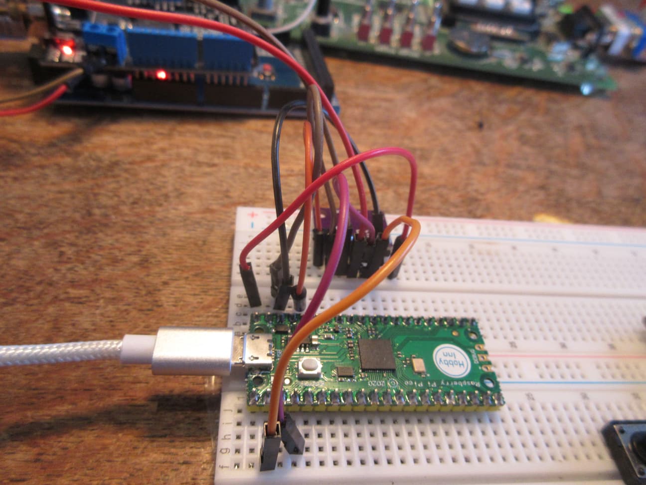
EDIT: updated code, results and photo

// RP2040 RPi Pico CAN Receive Example - note added INPUT_PULLUP to CAN0_INT
//
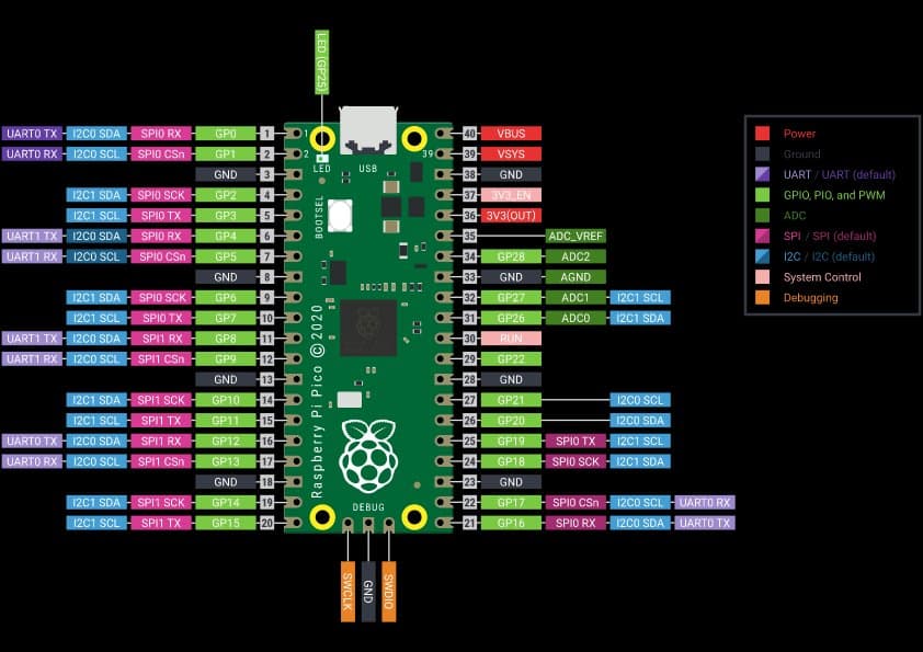
// RP2040 RPi PICO connections
// MCP2515 INT to RP2040 GP20
// MCP2515 SCK to RP2040 GP18 SPI0_SCK
// MCP2515  SI to RP2040 GP19 SPI0_TX
// MCP2515  SO to RP2040 GP16 SPI0_RX
// MCP2515  CS to RP2040 GP17 SPI0_CSn
// MCP2515 GND to RP2040 GND
// MCP2515 VCC to RP2040 GP 3.3V

#include <mcp_can.h>
#include <SPI.h>

long unsigned int rxId;
unsigned char len = 0;
unsigned char rxBuf[8];
char msgString[128];  // Array to store serial string

#define CAN0_INT 20  // for RP2040
MCP_CAN CAN0(17);    //

void setup() {
  Serial.begin(115200);
  delay(2000);
  Serial.println("\n\nRP2040 CAN MCP2515 shield Send/Receive test - MCP2515 Initialize");
  // Initialize MCP2515 baudrate of 250kb/s and the masks and filters disabled.
  //  check crystal frequency!! e.g. Canbus shield is 16MHz MCP2515 is 8MHz
  if (CAN0.begin(MCP_ANY, CAN_250KBPS, MCP_8MHZ) == CAN_OK)
    Serial.println("CAN Receive - MCP2515 Initialized Successfully!");
  else
    Serial.println("Error Initializing MCP2515...");
  CAN0.setMode(MCP_NORMAL);         // Set operation mode to normal so the MCP2515 sends acks to received data.
  pinMode(CAN0_INT, INPUT_PULLUP);  // Configuring pin for /INT input *** added PULLUP ***
  Serial.println("MCP2515 Library CAN Send/Receive Example\n enter space to send a frame");
}

void loop() {
  // check for data received
  if (!digitalRead(CAN0_INT))  // If CAN0_INT pin is low, read receive buffer
  {
    CAN0.readMsgBuf(&rxId, &len, rxBuf);    // Read data: len = data length, buf = data byte(s)
    if ((rxId & 0x80000000) == 0x80000000)  // Determine if ID is standard (11 bits) or extended (29 bits)
      sprintf(msgString, "Extended ID: 0x%.8lX  DLC: %1d  Data:", (rxId & 0x1FFFFFFF), len);
    else
      sprintf(msgString, "Standard ID: 0x%.3lX       DLC: %1d  Data: ", rxId, len);
    Serial.print(msgString);
    if ((rxId & 0x40000000) == 0x40000000) {  // Determine if message is a remote request frame.
      sprintf(msgString, " REMOTE REQUEST FRAME");
      Serial.print(msgString);
    } else {
      for (byte i = 0; i < len; i++) {
        sprintf(msgString, "0x%.2X ", rxBuf[i]);
        Serial.print(msgString);
      }
      Serial.print((char *)&rxBuf + 1);
    }
    Serial.println();
  }
  // transmit data when space entered on keyboard
  if (Serial.available()) {
    if (Serial.read() != ' ') return;
    static byte data[8] = { 0x00, 'R', 'P', 'p', 'i', 'c', 'o', 0};
    for (byte i = 0; i < 8; i++) {
      sprintf(msgString, " 0x%.2X", data[i]);
      Serial.print(msgString);
    }

    // send data:  ID = 0x100, Standard CAN Frame, Data length = 8 bytes, 'data' = array of data bytes to send
    byte sndStat = CAN0.sendMsgBuf(0x100, 0, 8, data);
    if (sndStat == CAN_OK) {
      Serial.println(" Message Sent Successfully!");
    } else {
      Serial.println(" Error Sending Message...");
    }
    data[0]++;  // increment first byte of data
  }
}

serial monitor output

RP2040 CAN MCP2515 shield Send/Receive test - MCP2515 Initialize
Entering Configuration Mode Successful!
Setting Baudrate Successful!
CAN Receive - MCP2515 Initialized Successfully!
MCP2515 Library CAN Send/Receive Example
 enter space to send a frame
Standard ID: 0x100       DLC: 8  Data: 0x00 0x4D 0x45 0x47 0x41 0x00 0x07 0x08 MEGA
Standard ID: 0x100       DLC: 8  Data: 0x01 0x4D 0x45 0x47 0x41 0x00 0x07 0x08 MEGA
 0x00 0x52 0x50 0x70 0x69 0x63 0x6F 0x00 Message Sent Successfully!
 0x01 0x52 0x50 0x70 0x69 0x63 0x6F 0x00 Message Sent Successfully!
Standard ID: 0x7DF       DLC: 8  Data: 0x02 0x54 0x57 0x41 0x49 0x00 0xAA 0xAA TWAI
Standard ID: 0x7DF       DLC: 8  Data: 0x03 0x54 0x57 0x41 0x49 0x00 0xAA 0xAA TWAI
Standard ID: 0x077       DLC: 8  Data: 0x11 0x50 0x49 0x43 0x32 0x34 0x00 0x00 PIC24
Extended ID: 0x00000077  DLC: 8  Data:0x11 0x50 0x49 0x43 0x32 0x34 0x00 0x00 PIC24
Extended ID: 0x00000077  DLC: 0  Data: REMOTE REQUEST FRAME
Standard ID: 0x40000077       DLC: 0  Data:  REMOTE REQUEST FRAME
Standard ID: 0x100       DLC: 8  Data: 0x00 0x00 0x00 0x00 0x00 0x00 0x00 0x00 
Standard ID: 0x100       DLC: 8  Data: 0x00 0x00 0x00 0x00 0x00 0x00 0x00 0x00

photo

So which one is connected to the RP Pi pico? The 3.3V one?
The 1050-transceiver datasheet says the 1050-tranceiver requires Vcc > 4.75
I supplied this

niren MCP2515-module with 3.3V from an arduino uno and the Uno does receive the data sended from the ESP32-S3-TJA1051 CAN-BUS

yes - do not connect 5V devices to a RPi pico it will damage the microcontroller

I have another question:

if the CAN-BUS is adjusted to 500 kbaud
what should a digital storage oscilloscope show as smallest pulse on the CAN-BUS ?
would this be 1 / 500000 = 0.000002 seconds = 2 µsec ?

With this I could definitely confirm / measure the real baudrate

oscilloscope plot of CAN 500KHz
image

the cursor shows pulse width of 2uSec

Hi @horace,

thank you for posting the screenshot and confirming that a single bit-length is 1 / baud.

if you still wish to use the Raspberry Pi pico with Canbus there is the Adafruit PiCowbell CAN Bus for Pico

or Adafruit RP2040 CAN Bus Feather with MCP2515 CAN Controller

Hi @horace

thank you for posting these boards.
I managed to make the RPico work with your code that interfaces to the MCP2515.

It was a problem of using the function-call CAN.setClockFrequency(8000000);

prior to
CAN.begin(500E3)) {

as mentioned by user @noiasca

void setup() {
  // ...
  CAN.setClockFrequency(8000000); // 8 MHz
  // ...
  CAN.begin(500E3)) {
 // ...
  CAN.onReceive(onReceive);
}

my Niren MCP2515-module which has the NXP 1050-tranceiver worked and was able to transmitt data with 500 kbaud to an arduino Uno connected to the same type of Niren MCP2515/NXP1050-tranceiver
even when supplied with 3.3V

The documentation of the MCP2515 can be improved by mentioning explicitly these details

Next step would be to find a demo-code that uses the PIO-functionality to create the CAN-BUS-controller. With finding such a library it would be sufficient to use a TJA1051 tranceiver which is able to create the 5V from a 3V supply.
This would perfectly match with the Rpico

have a look at can2040 project is a software CAN bus

I did look into it. This is "generalised" "C" not especially arduino

I have no knowledge how to adapt from "generalised" "C" to a arduino-compatible library
the can2040.c file looks like this

// Software CANbus implementation for rp2040
//
// Copyright (C) 2022,2023  Kevin O'Connor <kevin@koconnor.net>
//
// This file may be distributed under the terms of the GNU GPLv3 license.

#include <stdint.h> // uint32_t
#include <string.h> // memset
#include "RP2040.h" // hw_set_bits
#include "can2040.h" // can2040_setup
#include "hardware/regs/dreq.h" // DREQ_PIO0_RX1
#include "hardware/structs/dma.h" // dma_hw
#include "hardware/structs/iobank0.h" // iobank0_hw
#include "hardware/structs/padsbank0.h" // padsbank0_hw
#include "hardware/structs/pio.h" // pio0_hw
#include "hardware/structs/resets.h" // RESETS_RESET_PIO0_BITS

no idea if this could be transferred simply 1 to 1 into an arduino-library

will try to find such a arduino-library....

I found this library

I simply quote the documentation and leave it up to you to make up your own opinion about this documentation
image
and this is the example-sketch

//
/// Pico CAN test using can2040
//

#include <ACAN2040.h>

const uint8_t PIONUM0 = 0;
const uint8_t TXPIN0 = 1;
const uint8_t RXPIN0 = 2;
const uint32_t BITRATE0 = 125000UL;
const uint32_t SYSCLK = F_CPU;

void my_cb(struct can2040 *cd, uint32_t notify, struct can2040_msg *msg);
char *msg_to_str(struct can2040_msg *msg);

ACAN2040 can2040(PIONUM0, TXPIN0, RXPIN0, BITRATE0, SYSCLK, my_cb);
bool got_msg = false;
struct can2040_msg tx_msg, rx_msg;
struct can2040_stats can_stats;

///

void setup() {

  // start serial and wait for connection to serial monitor
  Serial.begin(115200);
  while (!Serial);
  Serial.printf("\n\nACAN2040 test, bitrate = %lu kbps, syscl = %lu mhz\n", BITRATE0, SYSCLK);

  // create a test CAN message
  tx_msg.id = 12345;
  tx_msg.dlc = 8;
  for (uint8_t i = 0; i < 8; i++) {
    tx_msg.data[i] = i + 90;
  }

  // start CAN
  Serial.printf("starting CAN bus\n");
  can2040.begin();

  Serial.printf("setup complete, free memory = %u bytes\n\n", rp2040.getFreeHeap());
  Serial.printf("type 's' to send a test message\n");
  Serial.printf("type 't' to stop CAN\n");
  Serial.printf("type 'b' to restart CAN\n");
  Serial.printf("type 't' for CAN statistics\n\n");
}

///

void loop() {

  // print received message
  if (got_msg) {
    got_msg = false;
    Serial.printf("received msg: %s\n", msg_to_str(&rx_msg));
  }

  // send a test message
  if (Serial.available()) {
    char c = Serial.read();

    switch (c) {
    case 's':
      Serial.printf("sending message: %s ... ", msg_to_str(&tx_msg));

      if (can2040.ok_to_send()) {
        if (can2040.send_message(&tx_msg)) {
          Serial.printf("ok\n");
        } else {
          Serial.printf("** error sending message\n");
        }
      } else {
        Serial.printf("** no space available to send\n");
      }

      break;

    case 't':
      can2040.get_statistics(&can_stats);
      Serial.printf("rx_total = %lu, tx_total = %lu, tx_attempt = %lu, parse_error = %lu\n",
                    can_stats.rx_total, can_stats.tx_total, can_stats.tx_attempt, can_stats.parse_error);
      break;

    case 'p':
      Serial.printf("stopping CAN\n");
      can2040.stop();
      break;

    case 'b':
      Serial.printf("restarting CAN\n");
      can2040.begin();
      break;
    }
  }
}

/// notify callback

void my_cb(struct can2040 * cd, uint32_t notify, struct can2040_msg * msg) {

  (void)(cd);
  Serial.printf("cb: notify event type = %lu\n", notify);

  switch (notify) {
  case CAN2040_NOTIFY_RX:
    Serial.printf("cb: message received\n");
    rx_msg = *msg;
    got_msg = true;
    break;
  case CAN2040_NOTIFY_TX:
    Serial.printf("cb: message sent ok\n");
    break;
  case CAN2040_NOTIFY_ERROR:
    Serial.printf("cb: an error occurred\n");
    break;
  default:
    Serial.printf("cb: unknown event type\n");
    break;
  }
}

/// format CAN message as a string

char *msg_to_str(struct can2040_msg * msg) {

  static char buf[64], buf2[8];

  sprintf(buf, "[ %lu ] [ %lu ] [ ", msg->id, msg->dlc);
  for (uint32_t i = 0; i < msg->dlc && i < 8; i++) {
    sprintf(buf2, "%u ", msg->data[i]);
    strcat(buf, buf2);
  }
  strcat(buf, " ] ");

  if (msg->id & CAN2040_ID_RTR) {
    strcat(buf, "R");
  }

  if (msg->id & CAN2040_ID_EFF) {
    strcat(buf, "X");
  }

  return buf;
}

end of documentation

The sketch compiles after installing the ACAN2040-library
I tested the code with 500 kbaud. As the receiver I used the Arduino Uno with the Iren MCP2515-module that is well tested to work with the ESP32 and other Arduino-unos
....
I connected a Adafruit TJA1051 to the Rpico that is checked to work with an ESP32

Not a single signal on the CAN-LOW / the CAN-HIGH-wire

The serial monitor shows

11:25:00.125 -> 
11:25:00.125 -> 
11:25:00.125 -> ACAN2040 test, bitrate = 500000 kbps, syscl = 133000000 mhz
11:25:00.125 -> starting CAN bus
11:25:00.125 -> setup complete, free memory = 251384 bytes
11:25:00.125 -> 
11:25:00.125 -> type 's' to send a test message
11:25:00.125 -> type 't' to stop CAN
11:25:00.125 -> type 'b' to restart CAN
11:25:00.125 -> type 't' for CAN statistics
11:25:00.125 -> 
11:25:03.457 -> sending message: [ 12345 ] [ 8 ] [ 90 91 92 93 94 95 96 97  ]  ... ok
11:25:06.949 -> sending message: [ 12345 ] [ 8 ] [ 90 91 92 93 94 95 96 97  ]  ... ok
11:25:08.643 -> sending message: [ 12345 ] [ 8 ] [ 90 91 92 93 94 95 96 97  ]  ... ok
11:25:10.807 -> sending message: [ 12345 ] [ 8 ] [ 90 91 92 93 94 95 96 97  ]  ... ok
11:25:11.795 -> sending message: [ 12345 ] [ 8 ] [ 90 91 92 93 94 95 96 97  ]  ... ** no space available to send

I conclude if there is some error-checking. The error-checking seems not to include some kind of ack-knowledge from the TJA1051-tranceiver

But I have some questions
The demo-code uses these constants

const uint8_t PIONUM0 = 0;
const uint8_t TXPIN0 = 1;
const uint8_t RXPIN0 = 2;
const uint32_t BITRATE0 = 500000UL; //125000UL;
const uint32_t SYSCLK = F_CPU;

no idea what PIONUM0 = 0; means
const uint8_t TXPIN0 = 1;
const uint8_t RXPIN0 = 2;

seems to be the TX and the RX pin
From what perspective pico transmittin / receiving ?
or tranceiver transmittin / receiving

do these definitions really mean RPico IO-pin 1 / IO-pin 2
or do I have to make some translation because the library engages the PIO-module?
If yes where can I find information about this translation?

To check if I connected the correct RPico-IO-pin:
What would be the typical signal directly measured on the correct RPi-io-pin when sending a can-message with the ACAN2040-library?

using the code from post 31 for a RPi Pico I connected a cjmcu-1051 transciver so

// RPi pico RP2050 GND    cjmcu-1051 GND
// RPi pico RP2050 VBUS   cjmcu-1051 VCC powers transciver
// RPi pico RP2050 3.3V   cjmcu-1051 VIO powers logic
// RPi pico RP2050 GP1    cjmcu-1051 CTX
// RPi pico RP2050 GP2    cjmcu-1051 CRX
// RPi pico RP2050 GND    cjmcu-1051 S   HIGH = TRX off, LOW = TRX on

works OK sending and receiving CAN packets

ACAN2040 test, bitrate = 250000 kbps, syscl = 133000000 mhz
starting CAN bus
setup complete, free memory = 251384 bytes

type 's' to send a test message
type 't' to stop CAN
type 'b' to restart CAN
type 't' for CAN statistics

sending message: [ 12345 ] [ 8 ] [ 90 91 92 93 94 95 96 97  ]  ... ok
rx_total = 0, tx_total = 0, tx_attempt = 1, parse_error = 0
cb: notify event type = 1048576
cb: message received
received msg: [ 256 ] [ 8 ] [ 7 77 69 71 65 0 7 8  ] 
cb: notify event type = 1048576
cb: message received
received msg: [ 256 ] [ 8 ] [ 8 77 69 71 65 0 7 8  ] 
sending message: [ 12345 ] [ 8 ] [ 90 91 92 93 94 95 96 97  ]  ... ok
cb: notify event type = 2097152
cb: message sent ok
sending message: [ 12345 ] [ 8 ] [ 90 91 92 93 94 95 96 97  ]  ... ok
cb: notify event type = 2097152
cb: message sent ok
received msg: [ 181 ] [ 8 ] [ 119 118 102 102 102 102 102 102  ] 
received msg: [ 2337835144 ] [ 8 ] [ 119 118 102 102 102 102 102 102  ] X
cb: notify event type = 1048576
cb: message received
received msg: [ 256 ] [ 8 ] [ 9 77 69 71 65 0 7 8  ] 
received msg: [ 256 ] [ 8 ] [ 10 77 69 71 65 0 7 8  ] 

RP2050
is this a somehow deviated RaspBerry Pi pico or do you mean RP2040?

can you please post a high resolution topview of your cjmcu-1051-board
my Adafruit CAN Bus tranceiver TJA1051 T3/can has only one Vcc which can be powered from 3V

So far my experience is

I uploaded the example code. Adjusted to 500 kbaud. This is the 1 to 1 copy from the arduino IDE

#include <ACAN2040.h>

const uint8_t PIONUM0 = 0;
const uint8_t TXPIN0 = 1;
const uint8_t RXPIN0 = 2;
const uint32_t BITRATE0 = 500000UL; //125000UL;
const uint32_t SYSCLK = F_CPU;

void my_cb(struct can2040 *cd, uint32_t notify, struct can2040_msg *msg);
char *msg_to_str(struct can2040_msg *msg);

ACAN2040 can2040(PIONUM0, TXPIN0, RXPIN0, BITRATE0, SYSCLK, my_cb);
bool got_msg = false;
struct can2040_msg tx_msg, rx_msg;
struct can2040_stats can_stats;

///

void setup() {

  // start serial and wait for connection to serial monitor
  Serial.begin(115200);
  while (!Serial);
  Serial.printf("\n\nACAN2040 test, bitrate = %lu kbps, syscl = %lu mhz\n", BITRATE0, SYSCLK);

  // create a test CAN message
  tx_msg.id = 12345;
  tx_msg.dlc = 8;
  for (uint8_t i = 0; i < 8; i++) {
    tx_msg.data[i] = i + 90;
  }

  // start CAN
  Serial.printf("starting CAN bus\n");
  can2040.begin();

  Serial.printf("setup complete, free memory = %u bytes\n\n", rp2040.getFreeHeap());
  Serial.printf("type 's' to send a test message\n");
  Serial.printf("type 't' to stop CAN\n");
  Serial.printf("type 'b' to restart CAN\n");
  Serial.printf("type 't' for CAN statistics\n\n");
}

///

void loop() {

  // print received message
  if (got_msg) {
    got_msg = false;
    Serial.printf("received msg: %s\n", msg_to_str(&rx_msg));
  }

  // send a test message
  if (Serial.available()) {
    char c = Serial.read();

    switch (c) {
    case 's':
      Serial.printf("sending message: %s ... ", msg_to_str(&tx_msg));

      if (can2040.ok_to_send()) {
        if (can2040.send_message(&tx_msg)) {
          Serial.printf("ok\n");
        } else {
          Serial.printf("** error sending message\n");
        }
      } else {
        Serial.printf("** no space available to send\n");
      }

      break;

    case 't':
      can2040.get_statistics(&can_stats);
      Serial.printf("rx_total = %lu, tx_total = %lu, tx_attempt = %lu, parse_error = %lu\n",
                    can_stats.rx_total, can_stats.tx_total, can_stats.tx_attempt, can_stats.parse_error);
      break;

    case 'p':
      Serial.printf("stopping CAN\n");
      can2040.stop();
      break;

    case 'b':
      Serial.printf("restarting CAN\n");
      can2040.begin();
      break;
    }
  }
}

/// notify callback

void my_cb(struct can2040 * cd, uint32_t notify, struct can2040_msg * msg) {

  (void)(cd);
  Serial.printf("cb: notify event type = %lu\n", notify);

  switch (notify) {
  case CAN2040_NOTIFY_RX:
    Serial.printf("cb: message received\n");
    rx_msg = *msg;
    got_msg = true;
    break;
  case CAN2040_NOTIFY_TX:
    Serial.printf("cb: message sent ok\n");
    break;
  case CAN2040_NOTIFY_ERROR:
    Serial.printf("cb: an error occurred\n");
    break;
  default:
    Serial.printf("cb: unknown event type\n");
    break;
  }
}

/// format CAN message as a string

char *msg_to_str(struct can2040_msg * msg) {

  static char buf[64], buf2[8];

  sprintf(buf, "[ %lu ] [ %lu ] [ ", msg->id, msg->dlc);
  for (uint32_t i = 0; i < msg->dlc && i < 8; i++) {
    sprintf(buf2, "%u ", msg->data[i]);
    strcat(buf, buf2);
  }
  strcat(buf, " ] ");

  if (msg->id & CAN2040_ID_RTR) {
    strcat(buf, "R");
  }

  if (msg->id & CAN2040_ID_EFF) {
    strcat(buf, "X");
  }
  return buf;
}

and tested sending. As receiver I used an Arduino Uno with a Niren MCP2515-CAN-controller with a NXP 1050-tranceiver.

I tested the Niren MCP2515-CAN-controller with a NXP 1050-tranceiver to be able to receive CAN-messages at 500 kbaud with

  1. another arduino Uno
  2. an ESP32 with TJA1051-tranceiver
  3. RaspBerry Pi pico with a a Niren MCP2515-CAN-controller with a NXP 1050-tranceiver

all there combinations were able to continiously receive messages even once every 50 millisceonds

despite to that the code like posted above did only transmitt a first message
claims from the second message to have transmitted it OK (whatever this means)
but the only thing I could see on the oscilloscope was signals while sending the first message
this is what the serial monitor shows

15:47:21.026 -> ACAN2040 test, bitrate = 500000 kbps, syscl = 133000000 mhz
15:47:21.026 -> starting CAN bus
15:47:21.026 -> setup complete, free memory = 251384 bytes
15:47:21.026 -> 
15:47:21.026 -> type 's' to send a test message
15:47:21.026 -> type 't' to stop CAN
15:47:21.026 -> type 'b' to restart CAN
15:47:21.026 -> type 't' for CAN statistics
15:47:21.026 -> 
15:47:35.240 -> sending message: [ 12345 ] [ 8 ] [ 90 91 92 93 94 95 96 97  ]  ... ok
15:47:52.755 -> sending message: [ 12345 ] [ 8 ] [ 90 91 92 93 94 95 96 97  ]  ... ok
15:54:06.362 -> sending message: [ 12345 ] [ 8 ] [ 90 91 92 93 94 95 96 97  ]  ... ok
15:54:07.211 -> sending message: [ 12345 ] [ 8 ] [ 90 91 92 93 94 95 96 97  ]  ... ok
15:54:07.871 -> sending message: [ 12345 ] [ 8 ] [ 90 91 92 93 94 95 96 97  ]  ... ** no space available to send
15:54:09.286 -> sending message: [ 12345 ] [ 8 ] [ 90 91 92 93 94 95 96 97  ]  ... ** no space available to send

So what? after 4 messages this library has a problem with qued messages?

@horace would you mind posting your full code with which you tested?

fixed typing error - code is (I am using 250KBS)

/// Pico CAN test using can2040

// RPi pico RP2040: can2040 project is a software CAN bus implementation for Raspberry Pi rp2040
//    https://github.com/KevinOConnor/can2040

// ACAN2040: Arduino wrapper library for Kevin O'Connor's CAN driver using the PIO of the RP2040
//   https://github.com/obdevel/ACAN2040/tree/main

// cjmcu-1051 CAN transciver wiring
//     https://www.circuitstate.com/tutorials/what-is-can-bus-how-to-use-can-interface-with-esp32-and-arduino/

// RPi pico RP2040 GND    cjmcu-1051 GND
// RPi pico RP2040 VBUS   cjmcu-1051 VCC powers transciver
// RPi pico RP2040 3.3V   cjmcu-1051 VIO powers logic
// RPi pico RP2040 GP1    cjmcu-1051 CTX
// RPi pico RP2040 GP2    cjmcu-1051 CRX
// RPi pico RP2040 GND    cjmcu-1051 S   HIGH = TRX off, LOW = TRX on

#include <ACAN2040.h>

const uint8_t PIONUM0 = 0;
const uint8_t TXPIN0 = 1;
const uint8_t RXPIN0 = 2;
const uint32_t BITRATE0 = 250000UL;
const uint32_t SYSCLK = F_CPU;

void my_cb(struct can2040 *cd, uint32_t notify, struct can2040_msg *msg);
char *msg_to_str(struct can2040_msg *msg);

ACAN2040 can2040(PIONUM0, TXPIN0, RXPIN0, BITRATE0, SYSCLK, my_cb);
bool got_msg = false;
struct can2040_msg tx_msg, rx_msg;
struct can2040_stats can_stats;

///

void setup() {

  // start serial and wait for connection to serial monitor
  Serial.begin(115200);
  while (!Serial);
  Serial.printf("\n\nACAN2040 test, bitrate = %lu kbps, syscl = %lu mhz\n", BITRATE0, SYSCLK);

  // create a test CAN message
  tx_msg.id = 12345;
  tx_msg.dlc = 8;
  for (uint8_t i = 0; i < 8; i++) {
    tx_msg.data[i] = i + 90;
  }

  // start CAN
  Serial.printf("starting CAN bus\n");
  can2040.begin();

  Serial.printf("setup complete, free memory = %u bytes\n\n", rp2040.getFreeHeap());
  Serial.printf("type 's' to send a test message\n");
  Serial.printf("type 't' to stop CAN\n");
  Serial.printf("type 'b' to restart CAN\n");
  Serial.printf("type 't' for CAN statistics\n\n");
}

///

void loop() {

  // print received message
  if (got_msg) {
    got_msg = false;
    Serial.printf("received msg: %s\n", msg_to_str(&rx_msg));
  }

  // send a test message
  if (Serial.available()) {
    char c = Serial.read();

    switch (c) {
    case 's':
      Serial.printf("sending message: %s ... ", msg_to_str(&tx_msg));

      if (can2040.ok_to_send()) {
        if (can2040.send_message(&tx_msg)) {
          Serial.printf("ok\n");
        } else {
          Serial.printf("** error sending message\n");
        }
      } else {
        Serial.printf("** no space available to send\n");
      }

      break;

    case 't':
      can2040.get_statistics(&can_stats);
      Serial.printf("rx_total = %lu, tx_total = %lu, tx_attempt = %lu, parse_error = %lu\n",
                    can_stats.rx_total, can_stats.tx_total, can_stats.tx_attempt, can_stats.parse_error);
      break;

    case 'p':
      Serial.printf("stopping CAN\n");
      can2040.stop();
      break;

    case 'b':
      Serial.printf("restarting CAN\n");
      can2040.begin();
      break;
    }
  }
}

/// notify callback

void my_cb(struct can2040 * cd, uint32_t notify, struct can2040_msg * msg) {

  (void)(cd);
  Serial.printf("cb: notify event type = %lu\n", notify);

  switch (notify) {
  case CAN2040_NOTIFY_RX:
    Serial.printf("cb: message received\n");
    rx_msg = *msg;
    got_msg = true;
    break;
  case CAN2040_NOTIFY_TX:
    Serial.printf("cb: message sent ok\n");
    break;
  case CAN2040_NOTIFY_ERROR:
    Serial.printf("cb: an error occurred\n");
    break;
  default:
    Serial.printf("cb: unknown event type\n");
    break;
  }
}

/// format CAN message as a string

char *msg_to_str(struct can2040_msg * msg) {

  static char buf[64], buf2[8];

  sprintf(buf, "[ %lu ] [ %lu ] [ ", msg->id, msg->dlc);
  for (uint32_t i = 0; i < msg->dlc && i < 8; i++) {
    sprintf(buf2, "%u ", msg->data[i]);
    strcat(buf, buf2);
  }
  strcat(buf, " ] ");

  if (msg->id & CAN2040_ID_RTR) {
    strcat(buf, "R");
  }

  if (msg->id & CAN2040_ID_EFF) {
    strcat(buf, "X");
  }

  return buf;
}


I connect GP1 to CTX and GP2 to CRX
VIO powers the logic to the RP2040 connected to 3.3V
VCC powers the CAN transciver requires 5V (I used VBUS)

see The Raspberry Pi Pico Pinout: Diagram & Coding Guide

after looking at your wiring picture again I found what was wrong very simple thing.
I had the Rx-wire plugged next to GP1 which is not GP2 but GND.

After correcting this transmission started working at 250 kbaud.
At 500 kbaud the Rpico does something weird what makes the IDE freeze when serial monitor is opened

No option for me

my setup works OK at 500K, e.g.

ACAN2040 test, bitrate = 500000 kbps, syscl = 133000000 mhz
starting CAN bus
setup complete, free memory = 251384 bytes

type 's' to send a test message
type 't' to stop CAN
type 'b' to restart CAN
type 't' for CAN statistics

received msg: [ 3411576968 ] [ 0 ] [  ] RX
received msg: [ 2337835144 ] [ 8 ] [ 119 118 102 102 102 102 102 102  ] X
cb: notify event type = 1048576
cb: message received
received msg: [ 256 ] [ 8 ] [ 0 77 69 71 65 0 7 8  ] 
received msg: [ 256 ] [ 8 ] [ 1 77 69 71 65 0 7 8  ] 
sending message: [ 12345 ] [ 8 ] [ 90 91 92 93 94 95 96 97  ]  ... ok
cb: notify event type = 2097152
cb: message sent ok
sending message: [ 12345 ] [ 8 ] [ 90 91 92 93 94 95 96 97  ]  ... ok
cb: notify event type = 2097152
cb: message sent ok
sending message: [ 12345 ] [ 8 ] [ 90 91 92 93 94 95 96 97  ]  ... ok
cb: notify event type = 2097152
cb: message sent ok
sending message: [ 12345 ] [ 8 ] [ 90 91 92 93 94 95 96 97  ]  ... ok
cb: notify event type = 2097152
cb: message sent ok
sending message: [ 12345 ] [ 8 ] [ 90 91 92 93 94 95 96 97  ]  ... ok
cb: notify event type = 2097152
cb: message sent ok
sending message: [ 12345 ] [ 8 ] [ 90 91 92 93 94 95 96 97  ]  ... ok
cb: notify event type = 2097152
cb: message sent ok
sending message: [ 12345 ] [ 8 ] [ 90 91 92 93 94 95 96 97  ]  ... ok
cb: notify event type = 2097152
cb: message sent ok
cb: notify event type = 1048576
cb: message received
received msg: [ 136 ] [ 8 ] [ 119 118 102 102 102 102 102 102  ] 

is the bus terminated correctly with 120ohm resistors?

what CAN transciever are you using?

I have ordered one of the Adafruit RP2040 CAN Bus Feather with MCP2515 CAN Controller

yes

too much hasseling with the Rpico-PIO-version.

if you need to use a RP2040 I would move to a Adafruit RP2040 CAN Bus Feather with MCP2515 CAN Controller - all on the one PCB - no problems with different logic levels, wires giving poor connections, etc
otherwise use an ESP32 and the ESP32-TWAI-CAN library with a CAN transciver

update using adafruit-rp2040-can-bus-feather
notes:

  1. select board Adafruit Feather RP2040 CAN (to get correct SPI pinout etc)
  2. crystal is 16MHz
  3. GPIO19 - CAN Chip Select pin in Arduino with PIN_CAN_CS.
  4. GPIO22 - CAN Interrupt pin in Arduino with PIN_CAN_INTERRUPT.

updated code:

// RP2040 RPi Pico CAN Receive Example - note added INPUT_PULLUP to CAN0_INT
//
// Note for RP2040_CAN select board Adafruit Feather RP2040 CAN
//

#include <mcp_can.h>
#include <SPI.h>

long unsigned int rxId;
unsigned char len = 0;
unsigned char rxBuf[8];
char msgString[128];  // Array to store serial string

#define CAN0_INT PIN_CAN_INTERRUPT  // for RP2040_CAN MCP2515
MCP_CAN CAN0(PIN_CAN_CS);    //

void setup() {
  Serial.begin(115200);
  delay(2000);
  Serial.println("\n\nRP2040 CAN (MCP2515 onboard) Send/Receive test - MCP2515 Initialize");
  // Initialize MCP2515 baudrate of 250kb/s and the masks and filters disabled.
  //  check crystal frequency!! 
  // e.g. Canbus shield/RP2040_CAN is 16MHz MCP2515 is 8MHz
  if (CAN0.begin(MCP_ANY, CAN_250KBPS, MCP_16MHZ) == CAN_OK)
    Serial.println("CAN Receive - MCP2515 Initialized Successfully!");
  else
    Serial.println("Error Initializing MCP2515...");
  CAN0.setMode(MCP_NORMAL);         // Set operation mode to normal so the MCP2515 sends acks to received data.
  pinMode(CAN0_INT, INPUT_PULLUP);  // Configuring pin for /INT input *** added PULLUP ***
  Serial.println("MCP2515 Library CAN Send/Receive Example\n enter space to send a frame");
}

void loop() {
  // check for data received
  if (!digitalRead(CAN0_INT))  // If CAN0_INT pin is low, read receive buffer
  {
    CAN0.readMsgBuf(&rxId, &len, rxBuf);    // Read data: len = data length, buf = data byte(s)
    if ((rxId & 0x80000000) == 0x80000000)  // Determine if ID is standard (11 bits) or extended (29 bits)
      sprintf(msgString, "Extended ID: 0x%.8lX  DLC: %1d  Data:", (rxId & 0x1FFFFFFF), len);
    else
      sprintf(msgString, "Standard ID: 0x%.3lX       DLC: %1d  Data: ", rxId, len);
    Serial.print(msgString);
    if ((rxId & 0x40000000) == 0x40000000) {  // Determine if message is a remote request frame.
      sprintf(msgString, " REMOTE REQUEST FRAME");
      Serial.print(msgString);
    } else {
      for (byte i = 0; i < len; i++) {
        sprintf(msgString, "0x%.2X ", rxBuf[i]);
        Serial.print(msgString);
      }
      Serial.print((char *)&rxBuf + 1);
    }
    Serial.println();
  }
  // transmit data when space entered on keyboard
  if (Serial.available()) {
    if (Serial.read() != ' ') return;
    static byte data[8] = { 0x00, 'R', 'P', 'i', 'C', 'A', 'N', 0};
    for (byte i = 0; i < 8; i++) {
      sprintf(msgString, " 0x%.2X", data[i]);
      Serial.print(msgString);
    }

    // send data:  ID = 0x100, Standard CAN Frame, Data length = 8 bytes, 'data' = array of data bytes to send
    byte sndStat = CAN0.sendMsgBuf(0x100, 0, 8, data);
    if (sndStat == CAN_OK) {
      Serial.println(" Message Sent Successfully!");
    } else {
      Serial.println(" Error Sending Message...");
    }
    data[0]++;  // increment first byte of data
  }
}

serial monitor output

RP2040 CAN (MCP2515 onboard)  Send/Receive test - MCP2515 Initialize
Entering Configuration Mode Successful!
Setting Baudrate Successful!
CAN Receive - MCP2515 Initialized Successfully!
MCP2515 Library CAN Send/Receive Example
 enter space to send a frame
 0x00 0x52 0x50 0x69 0x43 0x41 0x4E 0x00 Message Sent Successfully!
 0x01 0x52 0x50 0x69 0x43 0x41 0x4E 0x00 Message Sent Successfully!
Standard ID: 0x100       DLC: 8  Data: 0x0A 0x4D 0x45 0x47 0x41 0x00 0x07 0x08 MEGA
Standard ID: 0x088       DLC: 8  Data: 0x11 0x50 0x49 0x43 0x32 0x34 0x00 0x00 PIC24
 0x02 0x52 0x50 0x69 0x43 0x41 0x4E 0x00 Message Sent Successfully!
 0x03 0x52 0x50 0x69 0x43 0x41 0x4E 0x00 Message Sent Successfully!
Extended ID: 0x07788888  DLC: 8  Data:0x11 0x50 0x49 0x43 0x32 0x34 0x00 0x00 PIC24
Standard ID: 0x100       DLC: 8  Data: 0x0B 0x4D 0x45 0x47 0x41 0x00 0x07 0x08 MEGA

Thank you so much for your provided code. After days of failing, I finally got my CAN-Bus working on my ESP32-S3 with the SNHVD230 Transceiver.
You're a king