ESP32 CAN-BUS Demo-Code for Adafruit Adafruit CAN Pal - CAN Bus Transceiver

Hi Everybody,

I tryied to get a RP2040 to work with CAN-BUS MCP2515-module but I did not manage it.
I tried multiple libraries but I got none of them to work.

So I switched over to an ESP32-S3 which has an inbuild CAN-BUS-engine.
And only needs a CAN-BUS-tranceiver that transform the bits to CAN-BUS-standard.
Adafruit has a very nice CAN-BUS-Board that can be driven with 3V and creates the 5V for the CAN-BUS itself.

I did the same and tried multiple libraries.

Same problems some did not compile, some did not work
finally user @horace pointed me to this library
ESP32-TWAI-CAN library

There is only one rather poor example-code for this library which is somehow specialised to request the coolant-temperature of a car if you connect the ESP32 to the ODB2-socket in the car.

Though I don't got a car laying around on my table :wink: I started to modify the demo-code to be more informative and to be more general to better explain the principle how to use this library

So I finally have a working demo-code that demonstrates the basic principle.

ATTENTION ! 8 MHz-CAN-Bus modules require changing the library-sourcecode

If you use a MCP2515-can-bus module with a 8 MHz chrystal the source-code of the library must be changed
Most of these 8 MHz modules look like this


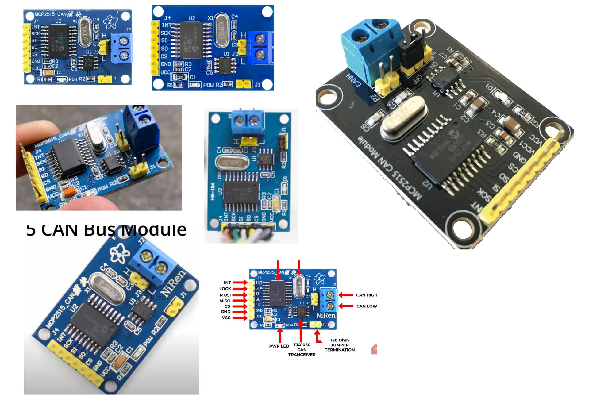
The chrystal is this component
image

Inside the library-file MCP2515.h comment / uncomment that line that matches the chystal-frequency on your MCP2515-module

A smart improvement that would take away this beginner-trap would be to modify the library to have this chrystal-frequency as a parameter in the constructor

// Copyright (c) Sandeep Mistry. All rights reserved.
// Licensed under the MIT license. See LICENSE file in the project root for full license information.

#ifndef ARDUINO_ARCH_ESP32

#ifndef MCP2515_H
#define MCP2515_H

#include <SPI.h>

#include "CANController.h"

//define MCP2515_DEFAULT_CLOCK_FREQUENCY 16e6 // defining a 16 MHz chrystal
#define MCP2515_DEFAULT_CLOCK_FREQUENCY 8e6   // defining a  8 MHz chrystal

I am using an arduino uno with the most common MCP2515-CAN-BUS-engine combined with a TJA 1050 CAN-BUS-tranceiver for receiving and on this Arduino Uno I have this code running for receiving

Code for receiver Arduino Uno with MCP2515-TJA1050

// MACRO-START * MACRO-START * MACRO-START * MACRO-START * MACRO-START * MACRO-START *
// a detailed explanation how these macros work is given in this tutorial
// https://forum.arduino.cc/t/comfortable-serial-debug-output-short-to-write-fixed-text-name-and-content-of-any-variable-code-example/888298

#define dbg(myFixedText, variableName) \
  Serial.print( F(#myFixedText " "  #variableName"=") ); \
  Serial.println(variableName);

#define dbgi(myFixedText, variableName,timeInterval) \
  { \
    static unsigned long intervalStartTime; \
    if ( millis() - intervalStartTime >= timeInterval ){ \
      intervalStartTime = millis(); \
      Serial.print( F(#myFixedText " "  #variableName"=") ); \
      Serial.println(variableName); \
    } \
  }

#define dbgc(myFixedText, variableName) \
  { \
    static long lastState; \
    if ( lastState != variableName ){ \
      Serial.print( F(#myFixedText " "  #variableName" changed from ") ); \
      Serial.print(lastState); \
      Serial.print( F(" to ") ); \
      Serial.println(variableName); \
      lastState = variableName; \
    } \
  }

#define dbgcf(myFixedText, variableName) \
  { \
    static float lastState; \
    if ( lastState != variableName ){ \
      Serial.print( F(#myFixedText " "  #variableName" changed from ") ); \
      Serial.print(lastState); \
      Serial.print( F(" to ") ); \
      Serial.println(variableName); \
      lastState = variableName; \
    } \
  }
// MACRO-END * MACRO-END * MACRO-END * MACRO-END * MACRO-END * MACRO-END * MACRO-END *

#include <CAN.h>


void PrintFileNameDateTime() {
  Serial.println( F("Code running comes from file ") );
  Serial.println( F(__FILE__) );
  Serial.print( F("  compiled ") );
  Serial.print( F(__DATE__) );
  Serial.print( F(" ") );
  Serial.println( F(__TIME__) );  
}


// easy to use helper-function for non-blocking timing
boolean TimePeriodIsOver (unsigned long &startOfPeriod, unsigned long TimePeriod) {
  unsigned long currentMillis  = millis();
  if ( currentMillis - startOfPeriod >= TimePeriod ) {
    // more time than TimePeriod has elapsed since last time if-condition was true
    startOfPeriod = currentMillis; // a new period starts right here so set new starttime
    return true;
  }
  else return false;            // actual TimePeriod is NOT yet over
}

unsigned long MyTestTimer = 0;                   // Timer-variables MUST be of type unsigned long
const byte    OnBoard_LED = 4;


void BlinkHeartBeatLED(int IO_Pin, int BlinkPeriod) {
  static unsigned long MyBlinkTimer;
  pinMode(IO_Pin, OUTPUT);
  
  if ( TimePeriodIsOver(MyBlinkTimer,BlinkPeriod) ) {
    digitalWrite(IO_Pin,!digitalRead(IO_Pin) ); 
  }
}


void setup() {
  Serial.begin(115200);
  while (!Serial);
  Serial.println("Setup-Start");
  PrintFileNameDateTime();

  Serial.println("CAN Receiver Callback");

  // start the CAN bus at 500 kbps
  //if (!CAN.begin(500E3)) {
  long kbpS = 500E3;
  Serial.print("CAN.begin(");
  Serial.print(kbpS);
  Serial.println(") done");
  
  if (!CAN.begin(kbpS)) {
    Serial.println("Starting CAN failed!");
    while (1);
  }
  Serial.println("Starting CAN successful!");

  // register the receive callback
  Serial.println("registering callback-function");
  Serial.println("exiting setup start listening....");
  CAN.onReceive(onReceive);
}

void loop() {
  BlinkHeartBeatLED(OnBoard_LED,250);
  yield();
  if ( TimePeriodIsOver(MyTestTimer,1000) ) {

  }  
}


void onReceive(int packetSize) {
  // received a packet
  Serial.print("Received ");

  if (CAN.packetExtended()) {
    Serial.print("extended ");
  }

  if (CAN.packetRtr()) {
    // Remote transmission request, packet contains no data
    Serial.print("RTR ");
  }

  Serial.print("packet with id 0x");
  Serial.print(CAN.packetId(), HEX);

  if (CAN.packetRtr()) {
    Serial.print(" and requested length ");
    Serial.println(CAN.packetDlc());
  } 
  else {
    Serial.print(" and length ");
    Serial.println(packetSize);

    // only print packet data for non-RTR packets
    while (CAN.available()) {
      Serial.print((char)CAN.read());
    }
    Serial.println();
  }

  Serial.println();
}

This is then printed to the serial monitor

19:47:28.134 -> Setup-Start
19:47:28.134 -> Code running comes from file 
19:47:28.134 -> C:\Arduino-Pure-Portable\arduino-1.8.19\portable\sketchbook\CAN-Bus-receiver-Demo-Code-002\CAN-Bus-receiver-Demo-Code-002.ino
19:47:28.134 ->   compiled Feb 11 2024 19:47:21
19:47:28.134 -> CAN Receiver Callback
19:47:28.134 -> CAN.begin(500000) done
19:47:28.134 -> Starting CAN successful!
19:47:28.134 -> registering callback-function
19:47:28.134 -> exiting setup start listening....
19:47:28.464 -> Received packet with id 0x7FF and length 8
19:47:28.512 -> 794HELLO
19:47:28.512 -> 
19:47:28.890 -> Received packet with id 0x7FF and length 8
19:47:28.890 -> 795HELLO
19:47:28.890 -> 
19:47:29.267 -> Received packet with id 0x7FF and length 8
19:47:29.314 -> 796HELLO
19:47:29.314 -> 
19:47:29.692 -> Received packet with id 0x7FF and length 8
19:47:29.692 -> 797HELLO
19:47:29.692 -> 
19:47:30.069 -> Received packet with id 0x7FF and length 8
19:47:30.069 -> 798HELLO
19:47:30.069 -> 
19:47:30.494 -> Received packet with id 0x7FF and length 8
19:47:30.494 -> 799HELLO
19:47:30.494 -> 
19:47:30.872 -> Received packet with id 0x7FF and length 8
19:47:30.872 -> 800HELLO
19:47:30.872 -> 
19:47:31.296 -> Received packet with id 0x7FF and length 8
19:47:31.296 -> 801HELLO
19:47:31.296 -> 
19:47:31.673 -> Received packet with id 0x7FF and length 8
19:47:31.673 -> 802HELLO
19:47:31.673 -> 
19:47:32.098 -> Received packet with id 0x7FF and length 8
19:47:32.098 -> 803HELLO
19:47:32.098 -> 
19:47:32.475 -> Received packet with id 0x7FF and length 8
19:47:32.475 -> 804HELLO
19:47:32.475 -> 
19:47:32.899 -> Received packet with id 0x7FF and length 8
19:47:32.899 -> 805HELLO
19:47:32.899 -> 
19:47:33.276 -> Received packet with id 0x7FF and length 8
19:47:33.276 -> 806HELLO
19:47:33.276 -> 
19:47:33.701 -> Received packet with id 0x7FF and length 8
19:47:33.701 -> 807HELLO
19:47:33.701 -> 
19:47:34.078 -> Received packet with id 0x7FF and length 8
19:47:34.078 -> 808HELLO
19:47:34.078 -> 
19:47:34.502 -> Received packet with id 0x7FF and length 8
19:47:34.502 -> 809HELLO
19:47:34.502 -> 
19:47:34.879 -> Received packet with id 0x7FF and length 8
19:47:34.879 -> 810HELLO
19:47:34.879 -> 
19:47:35.304 -> Received packet with id 0x7FF and length 8
19:47:35.304 -> 811HELLO
19:47:35.304 -> 
19:47:35.681 -> Received packet with id 0x7FF and length 8
19:47:35.681 -> 812HELLO
19:47:35.681 -> 
19:47:36.107 -> Received packet with id 0x7FF and length 8
19:47:36.107 -> 813HELLO
19:47:36.107 -> 
19:47:36.485 -> Received packet with id 0x7FF and length 8
19:47:36.485 -> 814HELLO
19:47:36.485 -> 

sending is done with this code modified from the OBD2-request-Demo
This code prints its parameters and the can-frame with ID length and 8 byte data

code for ESP32 tested on a ESP32-S3 connected to an Adafruit CAN Pal - CAN Bus Transceiver

// MACRO-START * MACRO-START * MACRO-START * MACRO-START * MACRO-START * MACRO-START *
// a detailed explanation how these macros work is given in this tutorial
// https://forum.arduino.cc/t/comfortable-serial-debug-output-short-to-write-fixed-text-name-and-content-of-any-variable-code-example/888298

#define dbg(myFixedText, variableName) \
  Serial.print( F(#myFixedText " "  #variableName"=") ); \
  Serial.println(variableName);

#define dbgi(myFixedText, variableName,timeInterval) \
  { \
    static unsigned long intervalStartTime; \
    if ( millis() - intervalStartTime >= timeInterval ){ \
      intervalStartTime = millis(); \
      Serial.print( F(#myFixedText " "  #variableName"=") ); \
      Serial.println(variableName); \
    } \
  }

#define dbgc(myFixedText, variableName) \
  { \
    static long lastState; \
    if ( lastState != variableName ){ \
      Serial.print( F(#myFixedText " "  #variableName" changed from ") ); \
      Serial.print(lastState); \
      Serial.print( F(" to ") ); \
      Serial.println(variableName); \
      lastState = variableName; \
    } \
  }

#define dbgcf(myFixedText, variableName) \
  { \
    static float lastState; \
    if ( lastState != variableName ){ \
      Serial.print( F(#myFixedText " "  #variableName" changed from ") ); \
      Serial.print(lastState); \
      Serial.print( F(" to ") ); \
      Serial.println(variableName); \
      lastState = variableName; \
    } \
  }
// MACRO-END * MACRO-END * MACRO-END * MACRO-END * MACRO-END * MACRO-END * MACRO-END *

/*
  Serial.begin(115200);
  Serial.println("Setup-Start");
  PrintFileNameDateTime();

  BlinkHeartBeatLED(OnBoard_LED,250);
  static unsigned long MyTestTimer;
  if ( TimePeriodIsOver(MyTestTimer,1000) ) {
*/

#include <ESP32-TWAI-CAN.hpp>

// Showcasing simple use of ESP32-TWAI-CAN library driver.

// Default for ESP32
const byte CAN_TX = 5; // which means connect GPIO-Pin with this number with the Tx-output on the CAN-transeiver
const byte CAN_RX = 4; // which means connect GPIO-Pin with this number with the Rx-input  on the CAN-transeiver

CanFrame rxFrame;
int myCounter;


void setup() {
  Serial.begin(115200);
  Serial.println("Setup-Start");
  PrintFileNameDateTime();
  Serial.println();

  // You can set custom size for the queues - those are default
  byte QueueSize = 5;
  ESP32Can.setRxQueueSize(QueueSize);
  ESP32Can.setTxQueueSize(QueueSize);
  Serial.print("ESP32Can.setRxQueueSize(");
  Serial.print(QueueSize);
  Serial.println(")");
  Serial.print("ESP32Can.setTxQueueSize(");
  Serial.print(QueueSize);
  Serial.println(")");

  int CAN_Speed = 500;
  Serial.print("ESP32Can.begin(ESP32Can.convertSpeed(");
  Serial.print(CAN_Speed);
  Serial.print("), CAN_TX=");
  Serial.print(CAN_TX);
  Serial.print(", CAN_RX=");
  Serial.print(CAN_RX);
  Serial.print(", 10, 10) )");
  Serial.println();

  if (ESP32Can.begin(ESP32Can.convertSpeed(CAN_Speed), CAN_TX, CAN_RX, 10, 10) ) {
    Serial.println("CAN bus started successfully!");
  }
  else {
    Serial.println("starting CAN bus failed!");
  }
}


void loop() {
  static unsigned long MyTestTimer;

  if ( TimePeriodIsOver(MyTestTimer, 400) ) {
    myCounter++;
    if (myCounter > 999) {
      myCounter = 0;
    }
    sendCanFrame('A', myCounter);
  }


  // You can set custom timeout, default is 1000 milliseconds
  if (ESP32Can.readFrame(rxFrame, 100)) {
    // Comment out if too many frames
    Serial.printf("Received frame: %03X  \r\n", rxFrame.identifier);
    if (rxFrame.identifier == 0x7E8) {  // Standard OBD2 frame responce ID
      Serial.printf("Collant temp: %3d°C \r\n", rxFrame.data[3] - 40); // Convert to °C
    }
  }

}

void sendCanFrame(uint8_t obdId, int Number) {
  char myDigitBuffer[10] = "         ";
  itoa(Number, myDigitBuffer, 10); // itoa convert integer to ASCII-coded char-array
  CanFrame myDataFrame = { 0 };
  //obdFrame.identifier = 0x7DF; // Default OBD2 address;
  myDataFrame.identifier = 0x7FF;
  myDataFrame.extd = 0;
  myDataFrame.data_length_code = 8;

  myDataFrame.data[0] = myDigitBuffer[0];
  myDataFrame.data[1] = myDigitBuffer[1];
  myDataFrame.data[2] = myDigitBuffer[2];
  myDataFrame.data[3] = 'H';
  myDataFrame.data[4] = 'e';
  myDataFrame.data[5] = 'l';
  myDataFrame.data[6] = 'l';
  myDataFrame.data[7] = 'o';
  // Accepts both pointers and references
  printCanFrame(myDataFrame);
  ESP32Can.writeFrame(myDataFrame);  // timeout defaults to 1 ms
}


void printCanFrame(CanFrame p_CAN_Frame) {
  Serial.println("sending CAN-frame");
  Serial.print("identifier=");
  Serial.print(p_CAN_Frame.identifier, HEX);
  Serial.print(" frame length=");
  Serial.print(p_CAN_Frame.data_length_code);
  Serial.print(" data as ASCII-Code#");

  for (byte IdxNr = 0; IdxNr < 8; IdxNr++) {
    Serial.print(char(p_CAN_Frame.data[IdxNr]) );
  }
  Serial.print("#");
  Serial.println();
}


// helper-functions
void PrintFileNameDateTime() {
  Serial.println( F("Code running comes from file ") );
  Serial.println( F(__FILE__) );
  Serial.print( F("  compiled ") );
  Serial.print( F(__DATE__) );
  Serial.print( F(" ") );
  Serial.println( F(__TIME__) );
}


// easy to use helper-function for non-blocking timing
boolean TimePeriodIsOver (unsigned long &startOfPeriod, unsigned long TimePeriod) {
  unsigned long currentMillis  = millis();
  if ( currentMillis - startOfPeriod >= TimePeriod ) {
    // more time than TimePeriod has elapsed since last time if-condition was true
    startOfPeriod = currentMillis; // a new period starts right here so set new starttime
    return true;
  }
  else return false;            // actual TimePeriod is NOT yet over
}


void BlinkHeartBeatLED(int IO_Pin, int BlinkPeriod) {
  static unsigned long MyBlinkTimer;
  pinMode(IO_Pin, OUTPUT);

  if ( TimePeriodIsOver(MyBlinkTimer, BlinkPeriod) ) {
    digitalWrite(IO_Pin, !digitalRead(IO_Pin) );
  }
}

The serial monitor shows this

20:11:04.336> ESP-ROM:esp32s3-20210327
20:11:04.336> Build:Mar 27 2021
20:11:04.336> rst:0x1 (POWERON),boot:0x8 (SPI_FAST_FLASH_BOOT)
20:11:04.336> SPIWP:0xee
20:11:04.336> mode:DIO, clock div:1
20:11:04.399> load:0x3fce3808,len:0x44c
20:11:04.399> load:0x403c9700,len:0xbd8
20:11:04.399> load:0x403cc700,len:0x2a80
20:11:04.399> entry 0x403c98d0
20:11:04.461> Setup-Start
20:11:04.461> Code running comes from file 
20:11:04.461> C:\Arduino-Pure-Portable\arduino-1.8.19\portable\sketchbook\ESP32-S3-CAN-BUS-transmitter-Demo-002\ESP32-S3-CAN-BUS-transmitter-Demo-002.ino
20:11:04.461>   compiled Feb 11 2024 20:02:31
20:11:04.461> 
20:11:04.461> ESP32Can.setRxQueueSize(5)
20:11:04.461> ESP32Can.setTxQueueSize(5)
20:11:04.461> ESP32Can.begin(ESP32Can.convertSpeed(500), CAN_TX=5, CAN_RX=4, 10, 10) )
20:11:04.461> CAN bus started successfully!
20:11:04.776> sending CAN-frame
20:11:04.776> identifier=7FF frame length=8 data as ASCII-Code#1<0> Hello#
20:11:05.154> sending CAN-frame
20:11:05.154> identifier=7FF frame length=8 data as ASCII-Code#2<0> Hello#
20:11:05.595> sending CAN-frame
20:11:05.595> identifier=7FF frame length=8 data as ASCII-Code#3<0> Hello#
20:11:05.973> sending CAN-frame
20:11:05.973> identifier=7FF frame length=8 data as ASCII-Code#4<0> Hello#
20:11:06.351> sending CAN-frame
20:11:06.351> identifier=7FF frame length=8 data as ASCII-Code#5<0> Hello#
20:11:06.792> sending CAN-frame
20:11:06.792> identifier=7FF frame length=8 data as ASCII-Code#6<0> Hello#
20:11:07.171> sending CAN-frame
20:11:07.171> identifier=7FF frame length=8 data as ASCII-Code#7<0> Hello#
20:11:07.548> sending CAN-frame
20:11:07.548> identifier=7FF frame length=8 data as ASCII-Code#8<0> Hello#
20:11:07.988> sending CAN-frame
20:11:07.988> identifier=7FF frame length=8 data as ASCII-Code#9<0> Hello#
20:11:08.366> sending CAN-frame
20:11:08.366> identifier=7FF frame length=8 data as ASCII-Code#10<0>Hello#

best regards Stefan

That is dependent on the crystal used. I think you may have a 16 MHz on the board and your code is for 8 MHz.

You do not have the MCP2515 module you indicated. The module shown is the CAN bus transceiver which takes the data from the CAN controller and translates them to the physical CAN bus levels which you stated you use.

From what I understand the RP2040 does not have a dedicated CAN peripheral on chip. I understand that Kevin ??? wrote code for the RP2040's PIO engine that can receive and send CAN packets. I will take a SWAG since I do not know or have the part suggest checking the clock divider for the PIO engine that is doing the CAN.

The library you are using with the Uno has 16MHz hard coded as the crystal speed. This is probably because most shields ship with a 16MHz crystal.

Niren style adaptors usually ship with an 8MHz crystal, therefore you need to modify the library to suit. (These half speed adaptors work OK, but cannot do CAN bus speeds above 500kBPS.)

title: ESP32 CAN-BUS Demo-Code for Adafruit Adafruit CAN Pal - CAN Bus Transceiver

Using ArduinoIntroductory Tutorials

which has the comment

then I posted the receiver code
which is titled

Code for receiver Arduino Uno with MCP2515-TJA1050

And the whole thread is no longr about the RP2040 as already mentioned in the title
best regards Stefan

@StefanL38, has this thread been curated to be in the Introductory Tutorials section?

Not sure what the word "curated" means.
If I remember right I started the thread myself in the introductory tutorials.
Do you think it should be moved to a different sub-forum?

1 Like

Instructions for creating Introductory Tutorials is here.

Thread moved.

I guess in the future I will post tutorials in general discussion or bar sports

If tutorials shall be moved to the tutorial-subforum only after moderator judgement make the tutorial sub-forum read-only

procedure to post tutorials since 9 months:

don't call others people work to be poor. That's odd behaviour. No need to blame that in a tutorial.

don't post "assumptions" in a tutorial. Figure out why you have this behaviour and explain it.
(check the resonator on your MCP2515 module, if it has not a 16Mhz resonator but an 8Mhz you need to define 8MHz, don't manipulate the BUS Speed, use the proper frequency).

no need to state. Your tutorial focuses on the ESP32. Explain what's needed to make it work on a ESP32.

as a summary comment:

add information to make it work. give hints to specialties, common errors etc.
specialists that know all this can jump over this
beginners will be glad to read it

it's unclear what library exactly you are using for the UNO code
if it is

name=CAN
version=0.3.1
author=Sandeep Mistry sandeep.mistry@gmail.com

there is a setter function:

void setClockFrequency(long clockFrequency);

to be as short as you:

I tried

  CAN.setClockFrequency(8000000); 

but with this modification of the receiver-code did not work.

I don't see what library you are using.
I told you what I have used.

my src/MCP2515.h doesn't have a line to "uncomment"
it looks like following

// Copyright (c) Sandeep Mistry. All rights reserved.
// Licensed under the MIT license. See LICENSE file in the project root for full license information.

#ifndef ARDUINO_ARCH_ESP32

#ifndef MCP2515_H
#define MCP2515_H

#include <SPI.h>

#include "CANController.h"

#define MCP2515_DEFAULT_CLOCK_FREQUENCY 16e6

so what you are using?

"did not work" means what?
compiler throws what error?
Baudrate remains unchanged?
Baudrate is set to any value <> 500.000?

[tldr]
I appreciate your question and your desire for a detailed response. In order to provide you with a comprehensive answer, it would be helpful to have more information about the specific libraries you are using in your project. Different libraries have different functionalities and nuances, so knowing which ones you are working with can help tailor my response to your specific situation.

Additionally, providing the source codeyou are working with would be extremely beneficial in offering you the most accurate and helpful advice. By examining the code you have written, I can provide more targeted guidance on how to approach your problem.

In the absence of specific details about the libraries you are using and the code you have written, I can offer some general advice on how to troubleshoot issues in your project. First, ensure that you have thoroughly read the documentation for the libraries you are using to understand their capabilities and limitations. This can often provide insights into potential solutions for your problem.

Secondly, consider reaching out to the community or support forums for the specific libraries you are using. Other developers who are familiar with the libraries may have encountered similar issues and can offer valuable insights or solutions to help you resolve your problem.

In conclusion, while I am happy to provide guidance and assistance with your project, having more details about the libraries you are using and the source code you have written will allow me to give you the most accurate and helpful advice. I encourage you to provide additional information so that I can offer you the best possible support in solving your issue. Thank you for your understanding and I 'm looking forward to help you further.

As sender I use an ESP32-S3 with this source-code and a Adafruit TJA1051 CAN-BUS-tranceiver

ESP32-S3 source-code

// MACRO-START * MACRO-START * MACRO-START * MACRO-START * MACRO-START * MACRO-START *
// a detailed explanation how these macros work is given in this tutorial
// https://forum.arduino.cc/t/comfortable-serial-debug-output-short-to-write-fixed-text-name-and-content-of-any-variable-code-example/888298

#define dbg(myFixedText, variableName) \
  Serial.print( F(#myFixedText " "  #variableName"=") ); \
  Serial.println(variableName);

#define dbgi(myFixedText, variableName,timeInterval) \
  { \
    static unsigned long intervalStartTime; \
    if ( millis() - intervalStartTime >= timeInterval ){ \
      intervalStartTime = millis(); \
      Serial.print( F(#myFixedText " "  #variableName"=") ); \
      Serial.println(variableName); \
    } \
  }

#define dbgc(myFixedText, variableName) \
  { \
    static long lastState; \
    if ( lastState != variableName ){ \
      Serial.print( F(#myFixedText " "  #variableName" changed from ") ); \
      Serial.print(lastState); \
      Serial.print( F(" to ") ); \
      Serial.println(variableName); \
      lastState = variableName; \
    } \
  }

#define dbgcf(myFixedText, variableName) \
  { \
    static float lastState; \
    if ( lastState != variableName ){ \
      Serial.print( F(#myFixedText " "  #variableName" changed from ") ); \
      Serial.print(lastState); \
      Serial.print( F(" to ") ); \
      Serial.println(variableName); \
      lastState = variableName; \
    } \
  }
// MACRO-END * MACRO-END * MACRO-END * MACRO-END * MACRO-END * MACRO-END * MACRO-END *

/*
  Serial.begin(115200);
  Serial.println("Setup-Start");
  PrintFileNameDateTime();

  BlinkHeartBeatLED(OnBoard_LED,250);
  static unsigned long MyTestTimer;
  if ( TimePeriodIsOver(MyTestTimer,1000) ) {
*/

#include <ESP32-TWAI-CAN.hpp>

// Showcasing simple use of ESP32-TWAI-CAN library driver.

// Default for ESP32
const byte CAN_TX = 5; // which means connect GPIO-Pin with this number with the Tx-output on the CAN-transeiver
const byte CAN_RX = 4; // which means connect GPIO-Pin with this number with the Rx-input  on the CAN-transeiver

CanFrame rxFrame;
int myCounter;


void setup() {
  Serial.begin(115200);
  Serial.println("Setup-Start");
  PrintFileNameDateTime();
  Serial.println();

  // You can set custom size for the queues - those are default
  byte QueueSize = 5;
  ESP32Can.setRxQueueSize(QueueSize);
  ESP32Can.setTxQueueSize(QueueSize);
  Serial.print("ESP32Can.setRxQueueSize(");
  Serial.print(QueueSize);
  Serial.println(")");
  Serial.print("ESP32Can.setTxQueueSize(");
  Serial.print(QueueSize);
  Serial.println(")");

  int CAN_Speed = 500;
  Serial.print("ESP32Can.begin(ESP32Can.convertSpeed(");
  Serial.print(CAN_Speed);
  Serial.print("), CAN_TX=");
  Serial.print(CAN_TX);
  Serial.print(", CAN_RX=");
  Serial.print(CAN_RX);
  Serial.print(", 10, 10) )");
  Serial.println();

  if (ESP32Can.begin(ESP32Can.convertSpeed(CAN_Speed), CAN_TX, CAN_RX, 10, 10) ) {
    Serial.println("CAN bus started successfully!");
  }
  else {
    Serial.println("starting CAN bus failed!");
  }
}


void loop() {
  static unsigned long MyTestTimer;

  if ( TimePeriodIsOver(MyTestTimer, 400) ) {
    myCounter++;
    if (myCounter > 999) {
      myCounter = 0;
    }
    sendCanFrame('A', myCounter);
  }


  // You can set custom timeout, default is 1000 milliseconds
  if (ESP32Can.readFrame(rxFrame, 100)) {
    // Comment out if too many frames
    Serial.printf("Received frame: %03X  \r\n", rxFrame.identifier);
    if (rxFrame.identifier == 0x7E8) {  // Standard OBD2 frame responce ID
      Serial.printf("Collant temp: %3d°C \r\n", rxFrame.data[3] - 40); // Convert to °C
    }
  }

}

void sendCanFrame(uint8_t obdId, int Number) {
  char myDigitBuffer[10] = "         ";
  itoa(Number, myDigitBuffer, 10); // itoa convert integer to ASCII-coded char-array
  CanFrame myDataFrame = { 0 };
  //obdFrame.identifier = 0x7DF; // Default OBD2 address;
  myDataFrame.identifier = 0x7FF;
  myDataFrame.extd = 0;
  myDataFrame.data_length_code = 8;

  myDataFrame.data[0] = myDigitBuffer[0];
  myDataFrame.data[1] = myDigitBuffer[1];
  myDataFrame.data[2] = myDigitBuffer[2];
  myDataFrame.data[3] = 'H';
  myDataFrame.data[4] = 'e';
  myDataFrame.data[5] = 'l';
  myDataFrame.data[6] = 'l';
  myDataFrame.data[7] = 'o';
  // Accepts both pointers and references
  printCanFrame(myDataFrame);
  ESP32Can.writeFrame(myDataFrame);  // timeout defaults to 1 ms
}


void printCanFrame(CanFrame p_CAN_Frame) {
  Serial.println("sending CAN-frame");
  Serial.print("identifier=");
  Serial.print(p_CAN_Frame.identifier, HEX);
  Serial.print(" frame length=");
  Serial.print(p_CAN_Frame.data_length_code);
  Serial.print(" data as ASCII-Code#");

  for (byte IdxNr = 0; IdxNr < 8; IdxNr++) {
    Serial.print(char(p_CAN_Frame.data[IdxNr]) );
  }
  Serial.print("#");
  Serial.println();
}


// helper-functions
void PrintFileNameDateTime() {
  Serial.println( F("Code running comes from file ") );
  Serial.println( F(__FILE__) );
  Serial.print( F("  compiled ") );
  Serial.print( F(__DATE__) );
  Serial.print( F(" ") );
  Serial.println( F(__TIME__) );
}


// easy to use helper-function for non-blocking timing
boolean TimePeriodIsOver (unsigned long &startOfPeriod, unsigned long TimePeriod) {
  unsigned long currentMillis  = millis();
  if ( currentMillis - startOfPeriod >= TimePeriod ) {
    // more time than TimePeriod has elapsed since last time if-condition was true
    startOfPeriod = currentMillis; // a new period starts right here so set new starttime
    return true;
  }
  else return false;            // actual TimePeriod is NOT yet over
}


void BlinkHeartBeatLED(int IO_Pin, int BlinkPeriod) {
  static unsigned long MyBlinkTimer;
  pinMode(IO_Pin, OUTPUT);

  if ( TimePeriodIsOver(MyBlinkTimer, BlinkPeriod) ) {
    digitalWrite(IO_Pin, !digitalRead(IO_Pin) );
  }
}

setting the CAN-Bus-baudrate of the ESP32-S3 to 500 kbs is done here

  int CAN_Speed = 500;
  Serial.print("ESP32Can.begin(ESP32Can.convertSpeed(");
  Serial.print(CAN_Speed);
  Serial.print("), CAN_TX=");
  Serial.print(CAN_TX);
  Serial.print(", CAN_RX=");
  Serial.print(CAN_RX);
  Serial.print(", 10, 10) )");
  Serial.println();

  if (ESP32Can.begin(ESP32Can.convertSpeed(CAN_Speed), CAN_TX, CAN_RX, 10, 10) ) {
    Serial.println("CAN bus started successfully!");
  }
  else {
    Serial.println("starting CAN bus failed!");
  }

This code uses the

#include <ESP32-TWAI-CAN.hpp>

library from here

As the receiver I use an Arduino Uno in combination with a NiRen-style
MCP2515 TJA1050 which looks like that
image
which has a 8 MHz chrystal

CAN.h and MCP2515-library
// Copyright (c) Sandeep Mistry. All rights reserved.
// Licensed under the MIT license. See LICENSE file in the project root for full license information.

#ifndef ARDUINO_ARCH_ESP32

#ifndef MCP2515_H
#define MCP2515_H

#include <SPI.h>

#include "CANController.h"

//define MCP2515_DEFAULT_CLOCK_FREQUENCY 16e6 // defining a 16 MHz chrystal
#define MCP2515_DEFAULT_CLOCK_FREQUENCY 8e6   // defining a  8 MHz chrystal


#if defined(ARDUINO_ARCH_SAMD) && defined(PIN_SPI_MISO) && defined(PIN_SPI_MOSI) && defined(PIN_SPI_SCK) && (PIN_SPI_MISO == 10) && (PIN_SPI_MOSI == 8) && (PIN_SPI_SCK == 9)
// Arduino MKR board: MKR CAN shield CS is pin 3, INT is pin 7
#define MCP2515_DEFAULT_CS_PIN          3
#define MCP2515_DEFAULT_INT_PIN         7
#else
#define MCP2515_DEFAULT_CS_PIN          10
#define MCP2515_DEFAULT_INT_PIN         2
#endif

class MCP2515Class : public CANControllerClass {

public:
  MCP2515Class();
  virtual ~MCP2515Class();

  virtual int begin(long baudRate);
  virtual void end();

  virtual int endPacket();

  virtual int parsePacket();

  virtual void onReceive(void(*callback)(int));

  using CANControllerClass::filter;
  virtual int filter(int id, int mask);
  using CANControllerClass::filterExtended;
  virtual int filterExtended(long id, long mask);

  virtual int observe();
  virtual int loopback();
  virtual int sleep();
  virtual int wakeup();

  void setPins(int cs = MCP2515_DEFAULT_CS_PIN, int irq = MCP2515_DEFAULT_INT_PIN);
  void setSPIFrequency(uint32_t frequency);
  void setClockFrequency(long clockFrequency);

  void dumpRegisters(Stream& out);

private:
  void reset();

  void handleInterrupt();

  uint8_t readRegister(uint8_t address);
  void modifyRegister(uint8_t address, uint8_t mask, uint8_t value);
  void writeRegister(uint8_t address, uint8_t value);

  static void onInterrupt();

private:
  SPISettings _spiSettings;
  int _csPin;
  int _intPin;
  long _clockFrequency;
};

extern MCP2515Class CAN;

#endif

#endif
// Copyright (c) Sandeep Mistry. All rights reserved.
// Licensed under the MIT license. See LICENSE file in the project root for full license information.

#ifndef ARDUINO_ARCH_ESP32

#include "MCP2515.h"

#define REG_BFPCTRL                0x0c
#define REG_TXRTSCTRL              0x0d

#define REG_CANCTRL                0x0f

#define REG_CNF3                   0x28
#define REG_CNF2                   0x29
#define REG_CNF1                   0x2a

#define REG_CANINTE                0x2b
#define REG_CANINTF                0x2c

#define FLAG_RXnIE(n)              (0x01 << n)
#define FLAG_RXnIF(n)              (0x01 << n)
#define FLAG_TXnIF(n)              (0x04 << n)

#define REG_RXFnSIDH(n)            (0x00 + (n * 4))
#define REG_RXFnSIDL(n)            (0x01 + (n * 4))
#define REG_RXFnEID8(n)            (0x02 + (n * 4))
#define REG_RXFnEID0(n)            (0x03 + (n * 4))

#define REG_RXMnSIDH(n)            (0x20 + (n * 0x04))
#define REG_RXMnSIDL(n)            (0x21 + (n * 0x04))
#define REG_RXMnEID8(n)            (0x22 + (n * 0x04))
#define REG_RXMnEID0(n)            (0x23 + (n * 0x04))

#define REG_TXBnCTRL(n)            (0x30 + (n * 0x10))
#define REG_TXBnSIDH(n)            (0x31 + (n * 0x10))
#define REG_TXBnSIDL(n)            (0x32 + (n * 0x10))
#define REG_TXBnEID8(n)            (0x33 + (n * 0x10))
#define REG_TXBnEID0(n)            (0x34 + (n * 0x10))
#define REG_TXBnDLC(n)             (0x35 + (n * 0x10))
#define REG_TXBnD0(n)              (0x36 + (n * 0x10))

#define REG_RXBnCTRL(n)            (0x60 + (n * 0x10))
#define REG_RXBnSIDH(n)            (0x61 + (n * 0x10))
#define REG_RXBnSIDL(n)            (0x62 + (n * 0x10))
#define REG_RXBnEID8(n)            (0x63 + (n * 0x10))
#define REG_RXBnEID0(n)            (0x64 + (n * 0x10))
#define REG_RXBnDLC(n)             (0x65 + (n * 0x10))
#define REG_RXBnD0(n)              (0x66 + (n * 0x10))

#define FLAG_IDE                   0x08
#define FLAG_SRR                   0x10
#define FLAG_RTR                   0x40
#define FLAG_EXIDE                 0x08

#define FLAG_RXM0                  0x20
#define FLAG_RXM1                  0x40


MCP2515Class::MCP2515Class() :
  CANControllerClass(),
  _spiSettings(10E6, MSBFIRST, SPI_MODE0),
  _csPin(MCP2515_DEFAULT_CS_PIN),
  _intPin(MCP2515_DEFAULT_INT_PIN),
  _clockFrequency(MCP2515_DEFAULT_CLOCK_FREQUENCY)
{
}

MCP2515Class::~MCP2515Class()
{
}

int MCP2515Class::begin(long baudRate)
{
  CANControllerClass::begin(baudRate);

  pinMode(_csPin, OUTPUT);

  // start SPI
  SPI.begin();

  reset();

  writeRegister(REG_CANCTRL, 0x80);
  if (readRegister(REG_CANCTRL) != 0x80) {
    return 0;
  }

  const struct {
    long clockFrequency;
    long baudRate;
    uint8_t cnf[3];
  } CNF_MAPPER[] = {
    {  (long)8E6, (long)1000E3, { 0x00, 0x80, 0x00 } },
    {  (long)8E6,  (long)500E3, { 0x00, 0x90, 0x02 } },
    {  (long)8E6,  (long)250E3, { 0x00, 0xb1, 0x05 } },
    {  (long)8E6,  (long)200E3, { 0x00, 0xb4, 0x06 } },
    {  (long)8E6,  (long)125E3, { 0x01, 0xb1, 0x05 } },
    {  (long)8E6,  (long)100E3, { 0x01, 0xb4, 0x06 } },
    {  (long)8E6,   (long)80E3, { 0x01, 0xbf, 0x07 } },
    {  (long)8E6,   (long)50E3, { 0x03, 0xb4, 0x06 } },
    {  (long)8E6,   (long)40E3, { 0x03, 0xbf, 0x07 } },
    {  (long)8E6,   (long)20E3, { 0x07, 0xbf, 0x07 } },
    {  (long)8E6,   (long)10E3, { 0x0f, 0xbf, 0x07 } },
    {  (long)8E6,    (long)5E3, { 0x1f, 0xbf, 0x07 } },

    { (long)16E6, (long)1000E3, { 0x00, 0xd0, 0x82 } },
    { (long)16E6,  (long)500E3, { 0x00, 0xf0, 0x86 } },
    { (long)16E6,  (long)250E3, { 0x41, 0xf1, 0x85 } },
    { (long)16E6,  (long)200E3, { 0x01, 0xfa, 0x87 } },
    { (long)16E6,  (long)125E3, { 0x03, 0xf0, 0x86 } },
    { (long)16E6,  (long)100E3, { 0x03, 0xfa, 0x87 } },
    { (long)16E6,   (long)80E3, { 0x03, 0xff, 0x87 } },
    { (long)16E6,   (long)50E3, { 0x07, 0xfa, 0x87 } },
    { (long)16E6,   (long)40E3, { 0x07, 0xff, 0x87 } },
    { (long)16E6,   (long)20E3, { 0x0f, 0xff, 0x87 } },
    { (long)16E6,   (long)10E3, { 0x1f, 0xff, 0x87 } },
    { (long)16E6,    (long)5E3, { 0x3f, 0xff, 0x87 } },
  };

  const uint8_t* cnf = NULL;

  for (unsigned int i = 0; i < (sizeof(CNF_MAPPER) / sizeof(CNF_MAPPER[0])); i++) {
    if (CNF_MAPPER[i].clockFrequency == _clockFrequency && CNF_MAPPER[i].baudRate == baudRate) {
      cnf = CNF_MAPPER[i].cnf;
      break;
    }
  }

  if (cnf == NULL) {
    return 0;
  }

  writeRegister(REG_CNF1, cnf[0]);
  writeRegister(REG_CNF2, cnf[1]);
  writeRegister(REG_CNF3, cnf[2]);

  writeRegister(REG_CANINTE, FLAG_RXnIE(1) | FLAG_RXnIE(0));
  writeRegister(REG_BFPCTRL, 0x00);
  writeRegister(REG_TXRTSCTRL, 0x00);
  writeRegister(REG_RXBnCTRL(0), FLAG_RXM1 | FLAG_RXM0);
  writeRegister(REG_RXBnCTRL(1), FLAG_RXM1 | FLAG_RXM0);

  writeRegister(REG_CANCTRL, 0x00);
  if (readRegister(REG_CANCTRL) != 0x00) {
    return 0;
  }

  return 1;
}

void MCP2515Class::end()
{
  SPI.end();

  CANControllerClass::end();
}

int MCP2515Class::endPacket()
{
  if (!CANControllerClass::endPacket()) {
    return 0;
  }

  int n = 0;

  if (_txExtended) {
    writeRegister(REG_TXBnSIDH(n), _txId >> 21);
    writeRegister(REG_TXBnSIDL(n), (((_txId >> 18) & 0x07) << 5) | FLAG_EXIDE | ((_txId >> 16) & 0x03));
    writeRegister(REG_TXBnEID8(n), (_txId >> 8) & 0xff);
    writeRegister(REG_TXBnEID0(n), _txId & 0xff);
  } else {
    writeRegister(REG_TXBnSIDH(n), _txId >> 3);
    writeRegister(REG_TXBnSIDL(n), _txId << 5);
    writeRegister(REG_TXBnEID8(n), 0x00);
    writeRegister(REG_TXBnEID0(n), 0x00);
  }

  if (_txRtr) {
    writeRegister(REG_TXBnDLC(n), 0x40 | _txLength);
  } else {
    writeRegister(REG_TXBnDLC(n), _txLength);

    for (int i = 0; i < _txLength; i++) {
      writeRegister(REG_TXBnD0(n) + i, _txData[i]);
    }
  }

  writeRegister(REG_TXBnCTRL(n), 0x08);

  bool aborted = false;

  while (readRegister(REG_TXBnCTRL(n)) & 0x08) {
    if (readRegister(REG_TXBnCTRL(n)) & 0x10) {
      // abort
      aborted = true;

      modifyRegister(REG_CANCTRL, 0x10, 0x10);
    }

    yield();
  }

  if (aborted) {
    // clear abort command
    modifyRegister(REG_CANCTRL, 0x10, 0x00);
  }

  modifyRegister(REG_CANINTF, FLAG_TXnIF(n), 0x00);

  return (readRegister(REG_TXBnCTRL(n)) & 0x70) ? 0 : 1;
}

int MCP2515Class::parsePacket()
{
  int n;

  uint8_t intf = readRegister(REG_CANINTF);

  if (intf & FLAG_RXnIF(0)) {
    n = 0;
  } else if (intf & FLAG_RXnIF(1)) {
    n = 1;
  } else {
    _rxId = -1;
    _rxExtended = false;
    _rxRtr = false;
    _rxLength = 0;
    return 0;
  }

  _rxExtended = (readRegister(REG_RXBnSIDL(n)) & FLAG_IDE) ? true : false;

  uint32_t idA = ((readRegister(REG_RXBnSIDH(n)) << 3) & 0x07f8) | ((readRegister(REG_RXBnSIDL(n)) >> 5) & 0x07);
  if (_rxExtended) {
    uint32_t idB = (((uint32_t)(readRegister(REG_RXBnSIDL(n)) & 0x03) << 16) & 0x30000) | ((readRegister(REG_RXBnEID8(n)) << 8) & 0xff00) | readRegister(REG_RXBnEID0(n));

    _rxId = (idA << 18) | idB;
    _rxRtr = (readRegister(REG_RXBnDLC(n)) & FLAG_RTR) ? true : false;
  } else {
    _rxId = idA;
    _rxRtr = (readRegister(REG_RXBnSIDL(n)) & FLAG_SRR) ? true : false;
  }
  _rxDlc = readRegister(REG_RXBnDLC(n)) & 0x0f;
  _rxIndex = 0;

  if (_rxRtr) {
    _rxLength = 0;
  } else {
    _rxLength = _rxDlc;

    for (int i = 0; i < _rxLength; i++) {
      _rxData[i] = readRegister(REG_RXBnD0(n) + i);
    }
  }

  modifyRegister(REG_CANINTF, FLAG_RXnIF(n), 0x00);

  return _rxDlc;
}

void MCP2515Class::onReceive(void(*callback)(int))
{
  CANControllerClass::onReceive(callback);

  pinMode(_intPin, INPUT);

  if (callback) {
    SPI.usingInterrupt(digitalPinToInterrupt(_intPin));
    attachInterrupt(digitalPinToInterrupt(_intPin), MCP2515Class::onInterrupt, LOW);
  } else {
    detachInterrupt(digitalPinToInterrupt(_intPin));
#ifdef SPI_HAS_NOTUSINGINTERRUPT
    SPI.notUsingInterrupt(digitalPinToInterrupt(_intPin));
#endif
  }
}

int MCP2515Class::filter(int id, int mask)
{
  id &= 0x7ff;
  mask &= 0x7ff;

  // config mode
  writeRegister(REG_CANCTRL, 0x80);
  if (readRegister(REG_CANCTRL) != 0x80) {
    return 0;
  }

  for (int n = 0; n < 2; n++) {
    // standard only
    writeRegister(REG_RXBnCTRL(n), FLAG_RXM0);
    writeRegister(REG_RXBnCTRL(n), FLAG_RXM0);

    writeRegister(REG_RXMnSIDH(n), mask >> 3);
    writeRegister(REG_RXMnSIDL(n), mask << 5);
    writeRegister(REG_RXMnEID8(n), 0);
    writeRegister(REG_RXMnEID0(n), 0);
  }

  for (int n = 0; n < 6; n++) {
    writeRegister(REG_RXFnSIDH(n), id >> 3);
    writeRegister(REG_RXFnSIDL(n), id << 5);
    writeRegister(REG_RXFnEID8(n), 0);
    writeRegister(REG_RXFnEID0(n), 0);
  }

  // normal mode
  writeRegister(REG_CANCTRL, 0x00);
  if (readRegister(REG_CANCTRL) != 0x00) {
    return 0;
  }

  return 1;
}

int MCP2515Class::filterExtended(long id, long mask)
{
  id &= 0x1FFFFFFF;
  mask &= 0x1FFFFFFF;

  // config mode
  writeRegister(REG_CANCTRL, 0x80);
  if (readRegister(REG_CANCTRL) != 0x80) {
    return 0;
  }

  for (int n = 0; n < 2; n++) {
    // extended only
    writeRegister(REG_RXBnCTRL(n), FLAG_RXM1);
    writeRegister(REG_RXBnCTRL(n), FLAG_RXM1);

    writeRegister(REG_RXMnSIDH(n), mask >> 21);
    writeRegister(REG_RXMnSIDL(n), (((mask >> 18) & 0x03) << 5) | FLAG_EXIDE | ((mask >> 16) & 0x03));
    writeRegister(REG_RXMnEID8(n), (mask >> 8) & 0xff);
    writeRegister(REG_RXMnEID0(n), mask & 0xff);
  }

  for (int n = 0; n < 6; n++) {
    writeRegister(REG_RXFnSIDH(n), id >> 21);
    writeRegister(REG_RXFnSIDL(n), (((id >> 18) & 0x03) << 5) | FLAG_EXIDE | ((id >> 16) & 0x03));
    writeRegister(REG_RXFnEID8(n), (id >> 8) & 0xff);
    writeRegister(REG_RXFnEID0(n), id & 0xff);
  }

  // normal mode
  writeRegister(REG_CANCTRL, 0x00);
  if (readRegister(REG_CANCTRL) != 0x00) {
    return 0;
  }

  return 1;
}

int MCP2515Class::observe()
{
  writeRegister(REG_CANCTRL, 0x80);
  if (readRegister(REG_CANCTRL) != 0x80) {
    return 0;
  }

  return 1;
}

int MCP2515Class::loopback()
{
  writeRegister(REG_CANCTRL, 0x40);
  if (readRegister(REG_CANCTRL) != 0x40) {
    return 0;
  }

  return 1;
}

int MCP2515Class::sleep()
{
  writeRegister(REG_CANCTRL, 0x01);
  if (readRegister(REG_CANCTRL) != 0x01) {
    return 0;
  }

  return 1;
}

int MCP2515Class::wakeup()
{
  writeRegister(REG_CANCTRL, 0x00);
  if (readRegister(REG_CANCTRL) != 0x00) {
    return 0;
  }

  return 1;
}

void MCP2515Class::setPins(int cs, int irq)
{
  _csPin = cs;
  _intPin = irq;
}

void MCP2515Class::setSPIFrequency(uint32_t frequency)
{
  _spiSettings = SPISettings(frequency, MSBFIRST, SPI_MODE0);
}

void MCP2515Class::setClockFrequency(long clockFrequency)
{
  _clockFrequency = clockFrequency;
}

void MCP2515Class::dumpRegisters(Stream& out)
{
  for (int i = 0; i < 128; i++) {
    byte b = readRegister(i);

    out.print("0x");
    if (i < 16) {
      out.print('0');
    }
    out.print(i, HEX);
    out.print(": 0x");
    if (b < 16) {
      out.print('0');
    }
    out.println(b, HEX);
  }
}

void MCP2515Class::reset()
{
  SPI.beginTransaction(_spiSettings);
  digitalWrite(_csPin, LOW);
  SPI.transfer(0xc0);
  digitalWrite(_csPin, HIGH);
  SPI.endTransaction();

  delayMicroseconds(10);
}

void MCP2515Class::handleInterrupt()
{
  if (readRegister(REG_CANINTF) == 0) {
    return;
  }

  while (parsePacket()) {
    _onReceive(available());
  }
}

uint8_t MCP2515Class::readRegister(uint8_t address)
{
  uint8_t value;

  SPI.beginTransaction(_spiSettings);
  digitalWrite(_csPin, LOW);
  SPI.transfer(0x03);
  SPI.transfer(address);
  value = SPI.transfer(0x00);
  digitalWrite(_csPin, HIGH);
  SPI.endTransaction();

  return value;
}

void MCP2515Class::modifyRegister(uint8_t address, uint8_t mask, uint8_t value)
{
  SPI.beginTransaction(_spiSettings);
  digitalWrite(_csPin, LOW);
  SPI.transfer(0x05);
  SPI.transfer(address);
  SPI.transfer(mask);
  SPI.transfer(value);
  digitalWrite(_csPin, HIGH);
  SPI.endTransaction();
}

void MCP2515Class::writeRegister(uint8_t address, uint8_t value)
{
  SPI.beginTransaction(_spiSettings);
  digitalWrite(_csPin, LOW);
  SPI.transfer(0x02);
  SPI.transfer(address);
  SPI.transfer(value);
  digitalWrite(_csPin, HIGH);
  SPI.endTransaction();
}

void MCP2515Class::onInterrupt()
{
  CAN.handleInterrupt();
}

MCP2515Class CAN;

#endif
// Copyright (c) Sandeep Mistry. All rights reserved.
// Licensed under the MIT license. See LICENSE file in the project root for full license information.

#ifndef CAN_H
#define CAN_H

#ifdef ARDUINO_ARCH_ESP32
#include "ESP32SJA1000.h"
#else
#include "MCP2515.h"
#endif

#endif

Arduino-Uno with MCP2512/TJA1050

// MACRO-START * MACRO-START * MACRO-START * MACRO-START * MACRO-START * MACRO-START *
// a detailed explanation how these macros work is given in this tutorial
// https://forum.arduino.cc/t/comfortable-serial-debug-output-short-to-write-fixed-text-name-and-content-of-any-variable-code-example/888298

#define dbg(myFixedText, variableName) \
  Serial.print( F(#myFixedText " "  #variableName"=") ); \
  Serial.println(variableName);

#define dbgi(myFixedText, variableName,timeInterval) \
  { \
    static unsigned long intervalStartTime; \
    if ( millis() - intervalStartTime >= timeInterval ){ \
      intervalStartTime = millis(); \
      Serial.print( F(#myFixedText " "  #variableName"=") ); \
      Serial.println(variableName); \
    } \
  }

#define dbgc(myFixedText, variableName) \
  { \
    static long lastState; \
    if ( lastState != variableName ){ \
      Serial.print( F(#myFixedText " "  #variableName" changed from ") ); \
      Serial.print(lastState); \
      Serial.print( F(" to ") ); \
      Serial.println(variableName); \
      lastState = variableName; \
    } \
  }

#define dbgcf(myFixedText, variableName) \
  { \
    static float lastState; \
    if ( lastState != variableName ){ \
      Serial.print( F(#myFixedText " "  #variableName" changed from ") ); \
      Serial.print(lastState); \
      Serial.print( F(" to ") ); \
      Serial.println(variableName); \
      lastState = variableName; \
    } \
  }
// MACRO-END * MACRO-END * MACRO-END * MACRO-END * MACRO-END * MACRO-END * MACRO-END *

#include <CAN.h>

unsigned long MyTestTimer = 0;                   // Timer-variables MUST be of type unsigned long
const byte    OnBoard_LED = 5;

byte counter = 0;

void PrintFileNameDateTime() {
  Serial.println( F("Code running comes from file ") );
  Serial.println( F(__FILE__) );
  Serial.print( F("  compiled ") );
  Serial.print( F(__DATE__) );
  Serial.print( F(" ") );
  Serial.println( F(__TIME__) );
}


// easy to use helper-function for non-blocking timing
boolean TimePeriodIsOver (unsigned long &startOfPeriod, unsigned long TimePeriod) {
  unsigned long currentMillis  = millis();
  if ( currentMillis - startOfPeriod >= TimePeriod ) {
    // more time than TimePeriod has elapsed since last time if-condition was true
    startOfPeriod = currentMillis; // a new period starts right here so set new starttime
    return true;
  }
  else return false;            // actual TimePeriod is NOT yet over
}


void BlinkHeartBeatLED(int IO_Pin, int BlinkPeriod) {
  static unsigned long MyBlinkTimer;
  pinMode(IO_Pin, OUTPUT);

  if ( TimePeriodIsOver(MyBlinkTimer, BlinkPeriod) ) {
    digitalWrite(IO_Pin, !digitalRead(IO_Pin) );
  }
}


void setup() {
  Serial.begin(115200);
  while (!Serial);
  Serial.println("Setup-Start");
  PrintFileNameDateTime();

  Serial.println("CAN Sender");

  // start the CAN bus at 500 kbps
  if (!CAN.begin(500E3)) {
    Serial.println("Starting CAN failed!");
    while (1);
  }
}


void loop() {
  BlinkHeartBeatLED(OnBoard_LED,250);

  if ( TimePeriodIsOver(MyTestTimer,1000) ) {
    counter++;
    sendCAN_Message();    
  }
}

char digitOne(byte number) {
  byte digit3;
  byte digit2;
  byte digit1;

  digit3 = number / 100;
  number = number - (digit3 * 100);
  digit2 = number / 10;
  digit1 = number - digit2 * 10;
  digit1 += '0';
  return digit1;
}

char digitTen(byte number) {
  byte digit3;
  byte digit2;

  digit3 = number / 100;
  number = number - (digit3 * 100);
  digit2 = number / 10;

  digit2 += '0';
  return digit2;
}

char digitHundred(byte number) {
  byte digit3;

  digit3 = number / 100;
  digit3 += '0';
  return digit3;
}


void sendCAN_Message() {
  // send packet: id is 11 bits, packet can contain up to 8 bytes of data
  Serial.print("Sending packet ... ");

  CAN.beginPacket(0x12);
  CAN.write(digitHundred(counter) );
  CAN.write(digitTen(counter) );
  CAN.write(digitOne(counter) );
  CAN.write('-');
  
  CAN.write('h');
  CAN.write('i');
  CAN.endPacket();

  Serial.println("done delay(1000)");

  delay(1000);
  // send extended packet: id is 29 bits, packet can contain up to 8 bytes of data
  Serial.print("Sending extended packet ... ");

  CAN.beginExtendedPacket(0xabcdef);
  CAN.write('w');
  CAN.write('o');
  CAN.write('r');
  CAN.write('l');
  CAN.write('d');
  CAN.endPacket();

  Serial.println("done");

}

ESP32-S3-code is set to real 500 kbps
in combination with receiver-code using default chrystal-frequency set to 16 MHz

define MCP2515_DEFAULT_CLOCK_FREQUENCY 16e6 // defining a 16 MHz chrystal

and then using in the Uno MCP2515-receiver-code

  CAN.setClockFrequency(8000000); // 8 MHz

result: communication did not work at all.
The can bus showed no bit-banging at all on the oscilloscope
flat lines on CAN-LOW and CAN-HIG

changing the ESP32-S3 sender-code to use CAN_Speed / 2 = 250 kbs

  if (ESP32Can.begin(ESP32Can.convertSpeed(CAN_Speed / 2), CAN_TX, CAN_RX, 10, 10) ) {
    Serial.println("CAN bus started successfully!");
  }
  else {
    Serial.println("starting CAN bus failed!");
  }

combined
with MCP2515.h using source-constant
define MCP2515_DEFAULT_CLOCK_FREQUENCY 16e6 // defining a 16 MHz chrystal
but in reality the niRen MCP2515-module is using an 8 MHz-chrystal

makes the communication work. Very plausible.
Code calculates with 16 Mhz
in reality using a clock of 8 MHz which is the half of 16 MHz
configuring Uno-MCP2515-receiver-code to use 500 kbs results in 250 kbs
which matches the ESP32-S3-sender-code which uses 250 kBs too.

it does not work with adding CAN.setClockFrequency(8000000); // 8 MHz

If I add in the Uno-MCP2515-receiver-code the line

  CAN.setClockFrequency(8000000); // 8 MHz

in combination with ESP32-S3-sender-code using 500 kps

  int CAN_Speed = 500;
  Serial.print("ESP32Can.begin(ESP32Can.convertSpeed(");
  Serial.print(CAN_Speed);
  Serial.print("), CAN_TX=");
  Serial.print(CAN_TX);
  Serial.print(", CAN_RX=");
  Serial.print(CAN_RX);
  Serial.print(", 10, 10) )");
  Serial.println();

  if (ESP32Can.begin(ESP32Can.convertSpeed(CAN_Speed), CAN_TX, CAN_RX, 10, 10) ) {
    Serial.println("CAN bus started successfully!");
  }

it does not work regardless of using

define MCP2515_DEFAULT_CLOCK_FREQUENCY 16e6 // defining a 16 MHz chrystal
//or
define MCP2515_DEFAULT_CLOCK_FREQUENCY 8e6 // defining a 8MHz chrystal

that is the reason why I posted
that the in the Uno MCP2515-library
MCP2515_DEFAULT_CLOCK_FREQUENCY must be adjusted to 8e6

are you using this library on the UNO?!?

You didn't show how and where you have put the line

CAN.setClockFrequency(8000000); // 8 MHz

but looking at the can bus source code it seems it has to be called before you call the .begin() member function as the setter only sets a member variable _clockFrequency while the .begin() uses the _clockFrequency and adopts some parameters.

-->
first set the clock frequency
than call begin

report what's happening.
If it is still not working, show your updated code.

I would have thought it must be the opposite order
first call begin
then call setClockFrequency

I am not at home atm. I can do new test tomorrow

Using this sketch

// MACRO-START * MACRO-START * MACRO-START * MACRO-START * MACRO-START * MACRO-START *
// a detailed explanation how these macros work is given in this tutorial
// https://forum.arduino.cc/t/comfortable-serial-debug-output-short-to-write-fixed-text-name-and-content-of-any-variable-code-example/888298

#define dbg(myFixedText, variableName) \
  Serial.print( F(#myFixedText " "  #variableName"=") ); \
  Serial.println(variableName);

#define dbgi(myFixedText, variableName,timeInterval) \
  { \
    static unsigned long intervalStartTime; \
    if ( millis() - intervalStartTime >= timeInterval ){ \
      intervalStartTime = millis(); \
      Serial.print( F(#myFixedText " "  #variableName"=") ); \
      Serial.println(variableName); \
    } \
  }

#define dbgc(myFixedText, variableName) \
  { \
    static long lastState; \
    if ( lastState != variableName ){ \
      Serial.print( F(#myFixedText " "  #variableName" changed from ") ); \
      Serial.print(lastState); \
      Serial.print( F(" to ") ); \
      Serial.println(variableName); \
      lastState = variableName; \
    } \
  }

#define dbgcf(myFixedText, variableName) \
  { \
    static float lastState; \
    if ( lastState != variableName ){ \
      Serial.print( F(#myFixedText " "  #variableName" changed from ") ); \
      Serial.print(lastState); \
      Serial.print( F(" to ") ); \
      Serial.println(variableName); \
      lastState = variableName; \
    } \
  }
// MACRO-END * MACRO-END * MACRO-END * MACRO-END * MACRO-END * MACRO-END * MACRO-END *

#include <CAN.h>


void PrintFileNameDateTime() {
  Serial.println( F("Code running comes from file ") );
  Serial.println( F(__FILE__) );
  Serial.print( F("  compiled ") );
  Serial.print( F(__DATE__) );
  Serial.print( F(" ") );
  Serial.println( F(__TIME__) );  
}


// easy to use helper-function for non-blocking timing
boolean TimePeriodIsOver (unsigned long &startOfPeriod, unsigned long TimePeriod) {
  unsigned long currentMillis  = millis();
  if ( currentMillis - startOfPeriod >= TimePeriod ) {
    // more time than TimePeriod has elapsed since last time if-condition was true
    startOfPeriod = currentMillis; // a new period starts right here so set new starttime
    return true;
  }
  else return false;            // actual TimePeriod is NOT yet over
}

unsigned long MyTestTimer = 0;                   // Timer-variables MUST be of type unsigned long
const byte    OnBoard_LED = 4;


void BlinkHeartBeatLED(int IO_Pin, int BlinkPeriod) {
  static unsigned long MyBlinkTimer;
  pinMode(IO_Pin, OUTPUT);
  
  if ( TimePeriodIsOver(MyBlinkTimer,BlinkPeriod) ) {
    digitalWrite(IO_Pin,!digitalRead(IO_Pin) ); 
  }
}


void setup() {
  Serial.begin(115200);
  while (!Serial);
  Serial.println("Setup-Start");
  PrintFileNameDateTime();

  CAN.setClockFrequency(8000000); // 8 MHz
  Serial.println("CAN.setClockFrequency(8000000); done");
  // register the receive callback
  CAN.onReceive(onReceive);
  Serial.println("registering callback-function done");

  // start the CAN bus at 500 kbps
  //if (!CAN.begin(500E3)) {
  long kbpS = 500E3;
  Serial.print("CAN.begin(");
  Serial.print(kbpS);
  Serial.println(") done");


  if (!CAN.begin(kbpS)) {
    Serial.println("Starting CAN failed!");
    while (1);
  }
  Serial.println("Starting CAN successful!");
  Serial.println("exiting setup start listening....");
}

void loop() {
  BlinkHeartBeatLED(OnBoard_LED,250);
  yield();
  if ( TimePeriodIsOver(MyTestTimer,1000) ) {

  }  
}


void onReceive(int packetSize) {
  // received a packet
  Serial.print("Received ");

  if (CAN.packetExtended()) {
    Serial.print("extended ");
  }

  if (CAN.packetRtr()) {
    // Remote transmission request, packet contains no data
    Serial.print("RTR ");
  }

  Serial.print("packet with id 0x");
  Serial.print(CAN.packetId(), HEX);

  if (CAN.packetRtr()) {
    Serial.print(" and requested length ");
    Serial.println(CAN.packetDlc());
  } 
  else {
    Serial.print(" and length ");
    Serial.println(packetSize);

    // only print packet data for non-RTR packets
    while (CAN.available()) {
      Serial.print((char)CAN.read());
    }
    Serial.println();
  }

  Serial.println();
}

makes the serial monitor show only a fraction of what should be printed

18:23:40.041 -> Setup-Start
18:23:40.041 -> Code running comes from file 
18:23:40.041 -> C:\Arduino-Pure-Portable\arduino-1.8.19\portable\sketchbook\Arduino-Uno-MCP2515-CAN-BUS-Demo-Code-002\Arduino-Uno-MCP2515-CAN-BUS-Demo-Code-002.ino
18:23:40.041 ->   compilSetup-Start
18:24:08.591 -> Code running comes from file 
18:24:08.591 -> C:\Arduino-Pure-Portable\arduino-1.8.19\portable\sketchbook\Arduino-Uno-MCP2515-CAN-BUS-Demo-Code-002\Arduino-Uno-MCP2515-CAN-BUS-Demo-Code-002.ino
18:24:08.591 ->   compil

the can-bus transmission runs but the serial monitor is not working (for what reason ever)

serial output should look like that

Setup-Start
18:27:31.197 -> Code running comes from file 
18:27:31.197 -> C:\Arduino-Pure-Portable\arduino-1.8.19\portable\sketchbook\Arduino-Uno-MCP2515-CAN-BUS-Demo-Code-002\Arduino-Uno-MCP25Setup-Start
18:28:34.294 -> Code running comes from file 
18:28:34.294 -> C:\Arduino-Pure-Portable\arduino-1.8.19\portable\sketchbook\Arduino-Uno-MCP2515-CAN-BUS-Demo-Code-002\Arduino-Uno-MCP2515-CAN-BUS-Demo-Code-002.ino
18:28:34.294 ->   compiled Feb 18 2024 18:28:27
18:28:34.294 -> CAN.begin(500000) done
18:28:34.294 -> Starting CAN successful!
18:28:34.294 -> exiting setup start listening....
18:28:34.294 -> registering callback-function done

After re-ordering the CAN-configuration and setup into this order

CAN.setClockFrequency(8000000); // 8 MHz

long kbpS = 500E3;
if (!CAN.begin(kbpS)) {
Serial.println("Starting CAN failed!");
while (1);
}
CAN.onReceive(onReceive);

the code runs and serial monitor works as expected

A high quality demo-code would include such information about the order in which things must be setup and that you must adjust the chrystalfrequency to the real value of the CAN-BUS-module to make it work at the specified baudrate

if you are looking for a simple example of the ESP32-TWAI-CAN library try

// ESP32-TWAI-CAN library using a cjmcu-1051 CAN transciver
//  adapted from  File>Examples>ESP32-TWAI-CAN>OBD2-querry

// ESP32-TWAI-CAN library
//    https://github.com/handmade0octopus/ESP32-TWAI-CAN

// cjmcu-1051 CAN transciver wiring
//     https://www.circuitstate.com/tutorials/what-is-can-bus-how-to-use-can-interface-with-esp32-and-arduino/

// ESP32 GND    cjmcu-1051 GND
// ESP32 5V     cjmcu-1051 VCC powers transciver
// ESP32 3.3V   cjmcu-1051 VIO powers logic
// ESP32 GPIO5  cjmcu-1051 CTX
// ESP32 GPIO4  cjmcu-1051 CRX
// ESP32 GND    cjmcu-1051 S   HIGH = TRX off, LOW = TRX on


#include <ESP32-TWAI-CAN.hpp>

// Simple sketch that transmits and receives CAN frames
// Showcasing simple use of ESP32-TWAI-CAN library driver.

// Default for ESP32
#define CAN_TX 5
#define CAN_RX 4

CanFrame rxFrame;

// transmit a test frame
void sendObdFrame(uint8_t obdId) {
  static byte data = 2;  // test value - increment every frame
  CanFrame obdFrame = { 0 };
  obdFrame.identifier = 0x7DF;  // Default OBD2 address;
  obdFrame.extd = 0;
  obdFrame.data_length_code = 8;
  obdFrame.data[0] = data;
  obdFrame.data[1] = 1;
  obdFrame.data[2] = obdId;
  obdFrame.data[3] = 0xAA;  // Best to use 0xAA (0b10101010) instead of 0
  obdFrame.data[4] = 0xAA;  // CAN works better this way as it needs
  obdFrame.data[5] = 0xAA;  // to avoid bit-stuffing
  obdFrame.data[6] = 0xAA;
  obdFrame.data[7] = 0xAA;
  // Accepts both pointers and references
  ESP32Can.writeFrame(obdFrame);  // timeout defaults to 1 ms
  data++;                         // increment for testing
  Serial.printf("Transmit frame: %03X: ", obdFrame.identifier);
  for (byte i = 0; i < 8; i++)
    Serial.printf(" 0x%.2X", obdFrame.data[i]);
  Serial.printf("\n");
}

void setup() {
  // Setup serial for debbuging.
  Serial.begin(115200);
  Serial.println("\n\nESP32-TWAI-CAN Send/Receive test -  Initialize");
  // Set pins
  ESP32Can.setPins(CAN_TX, CAN_RX);
  // You can set custom size for the queues - those are default
  ESP32Can.setRxQueueSize(5);
  ESP32Can.setTxQueueSize(5);
  // .setSpeed() and .begin() functions require to use TwaiSpeed enum,
  // but you can easily convert it from numerical value using .convertSpeed()
  ESP32Can.setSpeed(ESP32Can.convertSpeed(250));  //500));
  // You can also just use .begin()..
  if (ESP32Can.begin()) {
    Serial.println("CAN bus started!");
  } else {
    Serial.println("CAN bus failed!");
  }
  // or override everything in one command;
  // It is also safe to use .begin() without .end() as it calls it internally
  if (ESP32Can.begin(ESP32Can.convertSpeed(250), CAN_TX, CAN_RX, 10, 10)) {
    Serial.println("CAN bus started!");
  } else {
    Serial.println("CAN bus failed!");
  }
}

void loop() {
  // transmit data when space entered on keyboard
  if (Serial.available()) {
    if (Serial.read() != ' ') return;
    sendObdFrame(5);  // For coolant temperature
  }

  // frame received?  You can set custom timeout, default is 1000
  if (ESP32Can.readFrame(rxFrame, 1000)) {
    // print frame contents
    Serial.printf("Received frame: %03X: ", rxFrame.identifier);
    for (byte i = 0; i < 8; i++)
      Serial.printf(" 0x%.2X", rxFrame.data[i]);
    Serial.printf("\n");
  }
}

serial monitor output

ESP32-TWAI-CAN Send/Receive test -  Initialize
CAN bus started!
Transmit frame: 7DF:  0x02 0x01 0x05 0xAA 0xAA 0xAA 0xAA 0xAA
Transmit frame: 7DF:  0x03 0x01 0x05 0xAA 0xAA 0xAA 0xAA 0xAA
Received frame: 100:  0x00 0x01 0x02 0x03 0x04 0x05 0x06 0x07
Received frame: 100:  0x01 0x01 0x02 0x03 0x04 0x05 0x06 0x07
Received frame: 100:  0x18 0x01 0x02 0x03 0x04 0x05 0x06 0x07
Received frame: 100:  0x19 0x01 0x02 0x03 0x04 0x05 0x06 0x07
Received frame: 676:  0x66 0x66 0x66 0x66 0x66 0x66 0x66 0x00
Transmit frame: 7DF:  0x04 0x01 0x05 0xAA 0xAA 0xAA 0xAA 0xAA
Transmit frame: 7DF:  0x05 0x01 0x05 0xAA 0xAA 0xAA 0xAA 0xAA
Received frame: 100:  0x02 0x01 0x02 0x03 0x04 0x05 0x06 0x07
Received frame: 100:  0x03 0x01 0x02 0x03 0x04 0x05 0x06 0x07
Received frame: 12345678:  0x12 0x34 0x56 0x78 0x90 0x00 0x00 0x00
Received frame: 12345678:  0xAB 0xCD 0xEF 0x12 0x34 0x56 0x78 0x90

and from an ESP32 using a MCP2515

ESP32 CAN MCP2515 shield Send/Receive test - MCP2515 Initialize
Entering Configuration Mode Successful!
Setting Baudrate Successful!
CAN Receive - MCP2515 Initialized Successfully!
MCP2515 Library CAN Send/Receive Example
 enter space to send a frame
Standard ID: 0x7DF       DLC: 8  Data: 0x02 0x01 0x05 0xAA 0xAA 0xAA 0xAA 0xAA
Standard ID: 0x7DF       DLC: 8  Data: 0x03 0x01 0x05 0xAA 0xAA 0xAA 0xAA 0xAA
 0x00 0x01 0x02 0x03 0x04 0x05 0x06 0x07 Message Sent Successfully!
 0x01 0x01 0x02 0x03 0x04 0x05 0x06 0x07 Message Sent Successfully!
Standard ID: 0x100       DLC: 8  Data: 0x18 0x01 0x02 0x03 0x04 0x05 0x06 0x07
Standard ID: 0x100       DLC: 8  Data: 0x19 0x01 0x02 0x03 0x04 0x05 0x06 0x07
Standard ID: 0x676       DLC: 8  Data: 0x66 0x66 0x66 0x66 0x66 0x66 0x66 0x00
Standard ID: 0x7DF       DLC: 8  Data: 0x04 0x01 0x05 0xAA 0xAA 0xAA 0xAA 0xAA
Standard ID: 0x7DF       DLC: 8  Data: 0x05 0x01 0x05 0xAA 0xAA 0xAA 0xAA 0xAA
 0x02 0x01 0x02 0x03 0x04 0x05 0x06 0x07 Message Sent Successfully!
 0x03 0x01 0x02 0x03 0x04 0x05 0x06 0x07 Message Sent Successfully!
Extended ID: 0x12345678  DLC: 8  Data: 0x12 0x34 0x56 0x78 0x90 0x00 0x00 0x00
Extended ID: 0x12345678  DLC: 8  Data: 0xAB 0xCD 0xEF 0x12 0x34 0x56 0x78 0x9

photo of test setup two ESP32 one with a MCP2515 the other with a cjmcu-1051 CAN transciver

also connected was a Arduino Mega with a Canbus Shield V1.2, a RPi Pico with a MCP2515 shield, a PIC24 based mechatronics trainer and a USB-CAN dongle

That would be very interesting to see the code of the RaspBerry Pi pico driving the MCP2515 with writing what chrystal this MCP2515-module has and in combination with which CAN-BUS-tranceiver-chip this CAB-Bus-module works.

I tried to make a RaspBerry Pi pico work with an MCP2515 but had no success