Hello everyone,
I'm working on a data logger project using an ESP32 microcontroller. I have successfully interfaced the following components:
- Temperature Sensor(NTC)
- Current Sensor
- Voltage Sensor
- RTC Module (DS1307)-->I2c
- SD Card Module--->SPI
- Bluetooth Module
Observations:
- The SD card works fine when interfaced with the temperature, voltage, current sensors, and Bluetooth module.
- The RTC module (DS1307) also works correctly when used with the temperature, voltage, current sensors, and Bluetooth module.
Issue:
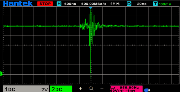
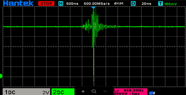
When I use the RTC and SD card together, I encounter the following problems:
- The SD card gets corrupted after some time.
- The RTC shows incorrect date and time during operation.
Additional Details:
- Both the SD card and RTC modules work perfectly in standalone tests.
- The issue only arises when both components are used simultaneously.
#include <esp_task_wdt.h>
#include "Measurements.h"
#include "SDcard.h"
#include "RTClib.h"
#include "Wire.h"
#include <string.h>
DS1307 rtc;
String Date = " ";
String Time = " ";
//Pin
#define currentSensor 33
#define voltageSensor 32
#define temperatureSensor 35
#define WDT_TIMEOUT 3
#define LED 26
#define LED2 10
#define BUILTIN_LED 2
#define timeIntervalForBT 1000
#define interrupt_pin 34
int sensorPin = 13;

// Time specific
#define timeIntervalForBT 1000
unsigned long startTime;
unsigned long lastTime;

uint64_t lastTick = 0;
uint64_t diff = 0;
// Flags
bool SDCAvailable = false;
bool logging = false;

// Global Vars
File file;
String filename = "/datalog.csv";
 int kmph =0;
// debug
bool stateL = false;
//SWS
int td=0;
float a=0;
int present =1;
int prev =1;
int present_Time = 0;
int prev_Time=0;

//Speed
volatile uint16_t call_counter = 0;
volatile uint16_t counter = 0;
uint32_t last_interrupt_time = 0;
uint32_t last_rising_time = 0;
uint32_t rising_diff = 0;

DateTime rtc_get_time() {
    return rtc.now();
}

// Function to check RTC connection by attempting communication
bool checkRTCConnection() {
  Wire.beginTransmission(0x68); // DS1307 RTC I2C address is 0x68
  uint8_t error = Wire.endTransmission();

  // If there is no error, the RTC is connected
  return (error == 0);
}
// Function to initialize the RTC
void initializeRTC() {
  if (!rtc.begin()) {
    Serial.println("RTC initialization failed! Check connections.");
    return; // Don't halt execution; allow reconnection attempts
  }

  if (!rtc.isrunning()) {
    Serial.println("RTC is not running. Setting current time...");
    rtc.adjust(DateTime(F(__DATE__), F(__TIME__))); // Set RTC to compile time
    Serial.println("RTC time has been set.");
  }
}
void IRAM_ATTR isr(){
  //interrupt function for speed
  // delayMicroseconds(10);
//  digitalWrite(LED, LOW);
  call_counter++;
  uint32_t current_time = millis();
  uint32_t interrupt_diff = current_time - last_interrupt_time;
  last_interrupt_time = millis();
  if (interrupt_diff < 10){
    return;
  }
  delayMicroseconds(10);
  if (digitalRead(interrupt_pin) == 0){
    return;
  }
  // digitalWrite(onboard_led, !(digitalRead(onboard_led)));
  rising_diff = millis() - last_rising_time;
  counter++;
  last_rising_time = millis();
}
void setup() {
  // put your setup code here, to run once:
  esp_task_wdt_init(WDT_TIMEOUT, true);
  esp_task_wdt_add(NULL);
  Serial.begin(115200);
  Serial2.begin(9600);
  pinMode(temperatureSensor,INPUT);
  pinMode(voltageSensor,INPUT);
  pinMode(currentSensor,INPUT);
  pinMode(interrupt_pin, INPUT_PULLUP);
  pinMode(BUILTIN_LED, OUTPUT);
  pinMode(LED, OUTPUT);
  pinMode(LED2, OUTPUT);
  attachInterrupt(interrupt_pin, isr, FALLING);
  initializeRTC();
  startSD();
  // initial values
  startTime = millis();
  startLogging();
}

void startSD(){
  int e = SD_init();
  // int e = 0;
  if (e == 0) {
    SDCAvailable = true;
  } else {
    showError(e);
  }
  getFileName();
}

void loop() {
  // Serial2.print("Current");
  // Serial2.println(calculate_Current());
  // Serial2.print("Voltage");
  // Serial2.println(calculate_Voltage());
  // Serial.print("ADC");
  // Serial2.println(analogRead(33));

  // Serial2.print("Temperature");
  // Serial2.println(calculate_temperature());
  Serial2.print("SWS");
  Serial2.println(calculate_speed(rising_diff));
   if (!checkRTCConnection()) {
    Date = "NA";
    Time = "NA";
//    Serial.println("RTC lost connection! Displaying NA...");
  } else {
    // If RTC is connected, fetch the current time
    DateTime now = rtc.now();

    // Format the date and time as strings
    Date = String(now.year()) + "/" + String(now.month()) + "/" + String(now.day());
    Time = String(now.hour()) + ":" + String(now.minute()) + ":" + String(now.second());
  }

   Serial2.println(Date);
   Serial2.println(Time);

  if(logging){
    unsigned long curTime = millis() - startTime;
    unsigned long displayCurTime = curTime / 1000;
    if(SD_openWrite(filename, calculate_Voltage(), calculate_Current(), calculate_temperature(),  calculate_speed(rising_diff),Date,Time, curTime)){
      digitalWrite(LED, LOW);
      digitalWrite(BUILTIN_LED, HIGH);
      esp_task_wdt_reset();
    } else {
      digitalWrite(LED, HIGH);
      digitalWrite(BUILTIN_LED, LOW);
      SD_init();
    }
    if (curTime > (lastTime + timeIntervalForBT)) {

      // bluetooth
      // Serial2.printf("#data,%.2f,%.2f,%.2f,%.2f,%.2f,%lu,%lu\n", calculate_Voltage(), calculate_Current(), calculate_temperature(),  SWS(), displayCurTime);
      lastTime = curTime;
    }

    esp_task_wdt_reset();
  }
}

void showError(int i) {
  Serial.println(i);
}

bool setFileName(String _fn){
    Serial.println("Saving file as: " + _fn);
    if (SD_setFileName(_fn)){
      filename = "/" + _fn + ".csv";
    }
}

void getFileName(){
  String filenameFromSD = SD_getFileName();
  filename = (filenameFromSD == " ")? "/datalog.csv" : filenameFromSD;

}
  // put your main code here, to run repeatedly:

void startLogging(){
  Serial.println("Starting logging");
  if(SD_writeFirstLine(filename)){
    digitalWrite(LED, HIGH);
    digitalWrite(BUILTIN_LED, HIGH);

  } else {
    digitalWrite(LED, LOW);
    digitalWrite(BUILTIN_LED, LOW);
  }
  logging = true;
  // if (SDCAvailable) { file = SD_openFile(filename); }
  startTime = millis();
  digitalWrite(LED, LOW);

}


void stopLogging(){
  Serial.println("Stopped logging");
  logging = false;
  digitalWrite(BUILTIN_LED, LOW);
  digitalWrite(LED, LOW);
  // if (SD_closeFile(file)){ Serial.println("file closed"); }
  // else { Serial.println("unable to close file");}
}

void countPulse(){
  uint64_t tdiff = millis() - lastTick;
  if (tdiff > 100){
    diff = tdiff;
  }
  lastTick = millis();
}


