First of all let me qualify my post by saying I have not been drinking or
smoking any left handed cigarettes....lol
I have worked with ESP32s on numerous occassions and feel fairly comfortable programming them and wiring inputs/outputs.
My latest project has both analog and digital inputs. The analog inputs work fine. But the digital inputs are not changing state.
I have used two different esp32s to make sure I did not have a defective processor.
I have tried different sketches as well.
So I decided to revert all the way back to a simple sketch that looks at
a dig input and turns on the builtin LED as a function of the digital input being closed or open.
Nothing works and I am now throwing myself at the mercy of this forum to tell me what stupid code or wiring configuration I am trying to use.
.......otherwise I am stumped.
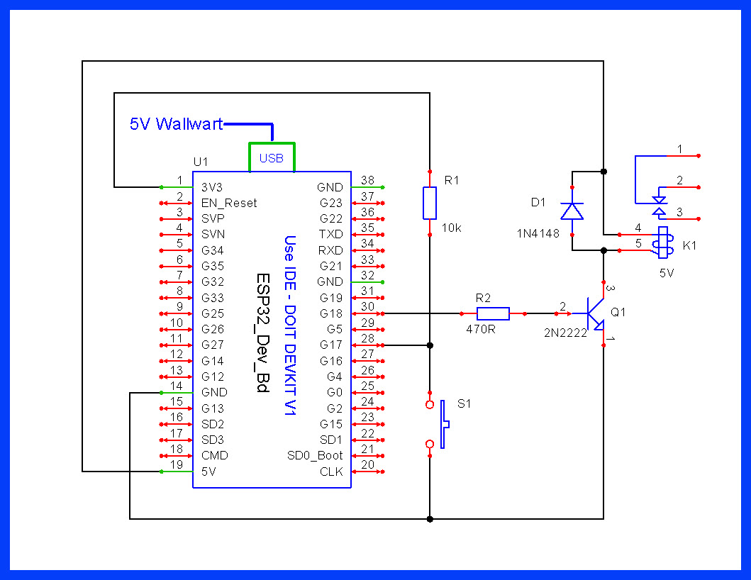
Note - Only GPOI inputs 6 -11 are unavailable for digital inputs as they are related to Flash.
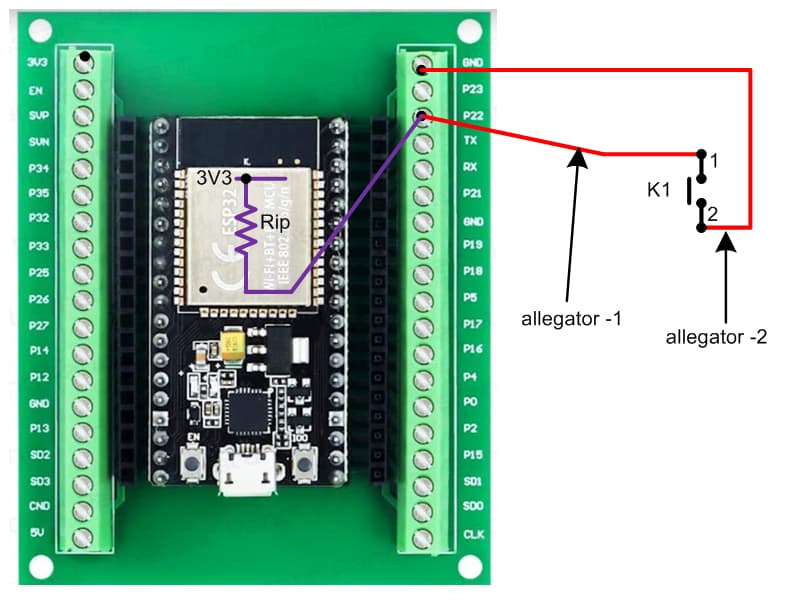
Wiring is using a 10Kohm resistor from the input (22) to ground. I have metered all connections. The input goes to 1 ohm with the alligator clips connected.
wiring pic:
so you have a 10k between 22 and GND,
and your aligator clips switch is also 22 and GND??
if my understanding is correct, then the state will definitely not change.
connect the 10k to 3v3 instead, or remove it and use internal pull up as LarryD suggests.
1. Screw one end of R1 directly with GND. 2. Twist together the other end of R1 and male header of alligator-1 and screw them into P22. 3. Connect allegator-1's mouth with one pin of K1. 4. Screw male header of allegator-2 with 3V3. Connect allegator-2's mouth with other pin of K1. 5. With an AVM, check the continuity. 6. Upload sketch of post #1. 7. Gently press K1. 8. Check that onboard blue LED of ESP2 has turned ON.
Your suggestion along with removing the 10K resistor works. But what is confusing the crap
out of me is why I have an ESP32 in the field right now that is monitoring a relay contact
with the 10 k resistor and the pinMode defined as 'INPUT' and it works perfectly.
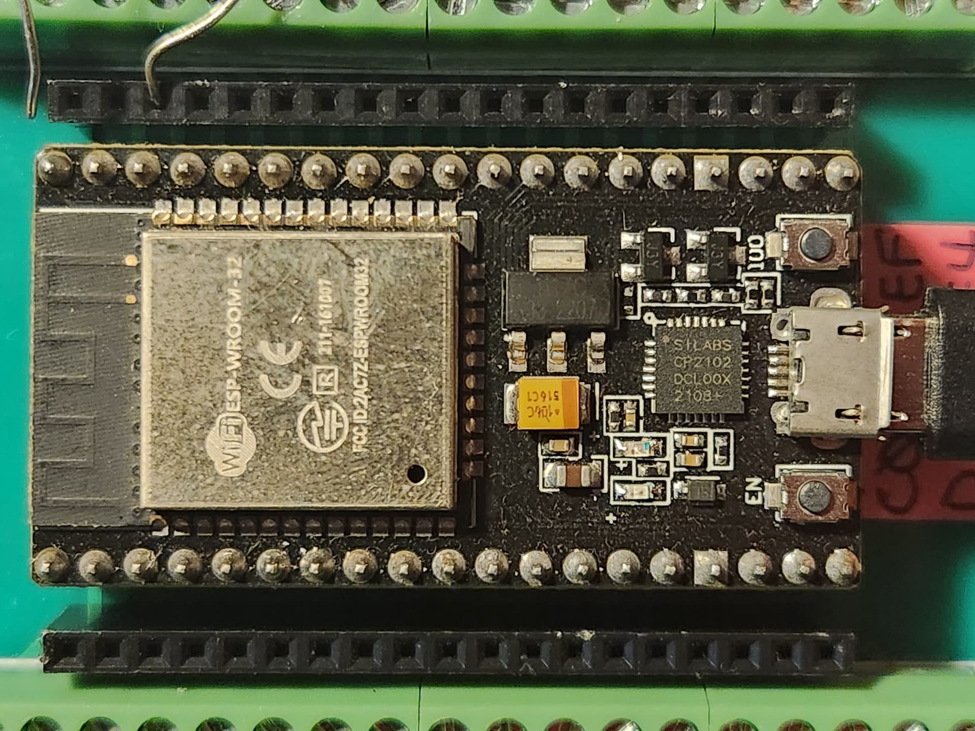
The only difference being the one installed is a 32 pin ESP WROVER model while this newest one
is a 38 pin WROVER. Would there be a difference in the two on how they handle digital inputs?
Evidently something is not the same....lol.
Thanks for your suggestion!
It had been over a year since I installed that project so I decided to break out my notes/drawings and sure enough you are absolutely correct in the wiring configuration. I thought I correctly remembered it but the onset of senility is now making me a tad concerned. Lol....
Well I now realize I am in violation of ESP wiring prootcol. I have been using VIN [+5V] on the 30 pin ESP32 to not only drive a digital input w/ external 10K resistor but also to energize one of those small black AGT icecube relays via a 2N2222. Are we supposed to find a 3v coil relay to use with an ESP. I know with a wall wart providing the power to an ESP through the USB port there is the +5v present at VIN. Is this something being done that is not "kosher?"
It is the WROOM 38 pin model. I believe it is the ESP DROVER (sp?) option from the IDE processor select listing. I do not have the IDE up right now. That one seems to work for me. I used the shorter ESP WROOM (30 pin) on an earlier project.