Hi!
I am currently working on a small ESP32-based project (see attached circuit) for a car, where a 12V LED strip should be dimmable and controlled by two different factors:
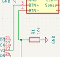
based on short/long press of an externally connected button (pins 3 and 4 from the connector at the top), the strip should be turned on/off and dimmed - this is realized using an IRLZ34N mosfet
depending on whether there is 12V between an external connection (pin 7 from the connector) and GND, the strip should be turned on/off - 12V is measured using the voltage divider at the bottom right of the circuit diagram
Power is provided as 12V externally (pins 1 and 2 from the connector), a 12V to 5V converter off amazon (Bauer Electronics DC/DC converter 5V 3A) then powers the ESP, which is an AzDelivery "Mini D1 ESP32". The DC/DC converter is not directly included in the diagram.
I have now noticed two different behaviors:
when powered via USB (same 12V/5V converter), the ESP boots normally and everything works as intended
when powered via the 5V pin (again same power source), the ESP boots only about 50% of the time. Rest of the time the red LED turns on, but it doesn't execute the program. Then, even pressing the reset button as often as I want doesn't change anything. It has to be powered off and on again repeatedly until it eventually works. I have the feeling if it doesn't work, it's very likely for it to still don't work on the next power cycle, but if it runs for once, it will likely also run the next try.
I would however like to power the ESP via the 5V pin, as I want to place it on a custom PCB. I already tried adding a 100uF capacitor on the 5V, as well as on the 12V side, but noticed no difference. In contrary to the attached circuit diagram, I also tried connecting all GND pins of the ESP, as I read about versions where the exact GND pin matters.
Also, power consumption should be rather low as I don't use WiFi and don't run any heavy computing.
Do you have any hints on what I might be missing or how I can further debug this problem?
Update: It is sufficient to plug a Micro-USB connector into the ESP of which only the positive cable is connected, when GND is provided over the header pins of course.
The other way around (GND over USB, 5V over the VCC pin), it does not work (reliably).
I think this indicates a problem on the positive side, assumably something is missing between my DC/DC converter and the ESPs VCC pin?
But really should be.
Can you show the specs of the converter and a photo of it, please?
Also a photo of how you have everything wired together, please.
I wouldn't recommend that. Instead, attach BTN+ to a GPIO and BTN- to GND, then configure the GPIO as INPUT_PULLUP. I'd use one of the plentifully available regular IO's instead of the special-purpose SVN.
Disconnect everything except the DC-DC converter and run blink. Supply the DC-DC converter with 12V from a battery or a bench power supply.
Doesn't sound good to me but you probably get away with it because the USB ends up being GND-connected to the rest of the circuit through a connection you've not mentioned (or perhaps realized is there). In any case, do NOT do this as a floating positive supply without GND can result in a potentially huge voltage being applied to the board, frying it. There's no control over this the way you're wiring it.
Current flows in a loop so a power supply problem is never isolated to either side.
Yup, sorry, the diagram above is just a screenshot off of KiCad, where I haven't added the DC/DC converter as it's not a component on the PCB and I don't know how to exclude things, but this is a different topic...
I don't have any additional specs from the DC/DC other than the ones from the picture below.
Please ignore the second (unlabeled) button on the breadboard, it was used for testing the 12V-measuring functionality. 12V rail on the left, 5V on the right, both share the same GND (connected at the top). The ESP unfortunately can't sit on the breadboard directly due to its two rows of headers per side. I wanted to not route 12V through the breadboard, but then needed it too often to not do so.
Hope the picture is somewhat identifiable.
The status LED, yeah. Can't blink the power LED (if your board has one) without power cycling the board; that's not what I mean.
Not sure what you mean, but your entire circuit has no form of isolation (and it doesn't need to have), so all GNDs can (and should) be connected.
Before someone comes in and yells "but ground loops!" - unlikely to be a problem here; if you're going to do audio or any other kind of analog signal processing, things may be different and I'd recommend a proper star ground setup. For now, don't worry about that and just make sure that all GNDs in your system are connected together.
@rsmls I will try with the minimal setup and blink program the next days and update you.
It's a switched voltage I want to watch. If present (around 12V, max 15V when car is running, corresponds to max 2.7V at the ESP), my LED strip is off, else it's on. State changes are implemented with a fade (slowly dimming up/down the light) and brightness can be set using long presses on the button.
As per the datasheet of the Mini D1 version I am using, the VCC pin is supposed to be powered with 5V. It also measures 5V when the board is powered via USB.
If you mean to power it via the 3V3 pin, yeah could be an option, although I currently have no way to convert to 3.3V.
Thanks; please do that (the blink testing). Note that this could be something as simple as a dodgy breadboard connection. The DC-DC converter itself looks fine in terms of specs, but the wire sticking into the breadboard...well, I'm not too sure of that. Run the blink test and especially try to give the breadboard a nudge as it runs; if you see the rhythm change or it misses a beat, it has likely reset. You can further monitor this by having a counter increment and output that to Serial so you can see if/when the counter has reset.
Having not had good experiences trying to power any ESP microntroller via a breadboard,
I would bet 25 cents on brownouts.
Do you have an old phone charger ?
( don't forget the ground)
Not having had any time for this project until today unfortunately, sorry!
I implemented the change regarding the button wiring (using INPUT_PULLUP and having connected the button directly between GPIO 26 and GND with no resistor - is this correct or do I need a pullup resistor between GPIO 26 and 3V3 @rsmls ?)
@ZX80 Yeah sounds reasonable. I tried using a phone charger before and encountered no problems.
With running both blink and my program, I wasn't able to reproduce the original issue. Let's interpret this as being fixed, although I'm not completely sure. I want to proceed however and order my PCB, hoping that it doesn't reoccur once everything is soldered into place.
I still have one question though: On every fresh power cycle the LED strip lights up for a fraction of a second. I thought this would have to do something with me using GPIO 23 for controlling the LED strip, which is also used for "SPI0:MOSI". But switching to GPIO 33, which by the pinout has no other label, doesn't change the behavior.
Can someone explain to me why this is happening and how I could prevent it?
The first lines in my setup() method are directly explicitly setting the LED output GPIO to zero:
const int LED_OUT_CHANNEL = 0;
const int BUTTON_GPIO = 26;

pinMode(LED_OUT_GPIO, ANALOG);
ledcAttachPin(LED_OUT_GPIO, LED_OUT_CHANNEL);
ledcSetup(LED_OUT_CHANNEL, 1000, 8);
ledcWrite(LED_OUT_CHANNEL, 0);
Yeah, that's possible. Apparently there's a very brief voltage spike on the GPIO at startup.
Note that it's only the 4th line of code where you set the output channel to zero. There's quite a bit happening before that point. It may help to start setup() with writing the LED GPIO LOW and then setting the LED GPIO as OUTPUT.
However, there's a good chance you'll still see this momentary flash. Is it a real problem? If not, I'd just ignore it; you can manage it out, but it'll take some additional hardware, and usually it's not really worth the trouble.
Can you shortly outline what kind of circuit would be necessary to avoid this flash? I tried adding a 100µF capacitor in parallel to the LED strip, can't tell if it changed the flash, but it obviously adds a looong fade-out when turning off the light.
Sadly the original problem just reoccurred (everything was fine at first, did some last tests before wanting to order the PCB):
After providing 12V to the breadboard, the ESP's status light lit up, but the program didn't work (doesn't react to the button / 12V sensing functionality). I also noticed that the initial flash of the LED strip doesn't happen in this case. I re-powered it at least 15 times without changes in the behavior and also wiggled every connection in between, even the whole breadbord, didn't help. Also tried the ESPs reset button.
Then, without moving things too much, I provided 5V via a cut-in-half USB cable with its other ends also stuffed into the 5V breadboard rails, so still running through those dodgy "wire stuffed into breadboard" connections, and it ran immediately.
Switched back to the original way of powering again, and now this one works just fine as well. And now it's reliable, even after another 30+ power cycles. Until it isn't anymore some time soon...
As much as I would love the breadboard and my dodgy cabling to be the reason, I don't think that's it. Haven't switched to running blink in this scenario, as it was clear that the initial LED flash was missing.
Maybe, maybe not. Hard to tell at this point. Sometimes an external power supply comes on a little slow, locking a microcontroller into a reset state. That's a bit of a wild guess though and as long as the problem cannot be reproduced reliably, it'll be hard to figure out what exactly is going on.
You could make a circuit that only connects the GPIO to the MOSFET gate a brief while after the power comes on. There are many ways to do this, ranging from a small R/C circuit and a single transistor, to something involving a 555 IC and/or a CMOS switch, and many others...
I was thinking something like this, so I left the 12V side powered and only disconnected/reconnected the positive 5V cable between breadboard and ESP to leave the DC/DC converter running.
But then I seem to have to order the PCB and see if it happens again. Thanks anyway for your support, much appreciated!
Ah sure, thanks! Might give this a try for version 2 or so.
You have two major problems.
The D1 mini is poorly designed, you are using the IRLZ34N.
The D1 reset circuits were designed wrong. It resets differently depending on whether it is powered from USB or 5V in. Both circuits are wrong but the USB boot seems to work for some reason.
The IRLZ34N may or may not work with a 3.3V gate voltage.
If you want something reliable, I suggest a different ESP32 board and a driver circuit for the MOSFET.
This is a suitable explanation for what I'm seeing here! The small form factor was what made me buy it... All of my other ESP32 models are in use at the moment, else I would've long tried another one. Argh.
What exactly do you mean by this? I've been using these a lot to control 12V LED strips with 3.3V gate voltage. What kind of problems could I be facing and can you point me to a suitable driver circuit?
At ~1A it is probably OK.
However, I would use an IRLR6225 MOSFET. The Rds(on) at Vgs=2.5V is only 5.2mΩ max.
With 2A of current, the maximum power dissipation is only 21mW (even less with 3.3V drive). It will stay cool even at an ambient temperature at high as 70ºC (like inside a car on a hot day).
It is a SMD part but the pin spacing is larger than the IRLZ34 so should be no problem to solder.
Digi-Key and Mouser have them in stock.
Will you be using a new ESP board?
If you don't use WiFi why the ESP?
Thanks, seems to be a good alternative. I couldn't find such a value for the IRLZ34N however, where did you find the 21mW at 2A?
I found a resistance of 1.25 Ohms at 70°C for the IRLZ34N, which would result in 5W of heat dissipation?! Thats 238x as much as the IRLR6225 - please tell me I'm wrong
Yeah that's the plan. I want it to be small and I also only need 3 GPIOs, so I was thinking a ESP32-C3 Mini or ESP32-C6 Mini from waveshare.
Valid question! Honestly it just was what I had lying around. The other week I had the idea it could be a handy feature to control the light via a web page, I might build that feature at some time, might also not. It's probably more realistic and useful when the thing controls more than just one light in the car (which is a camper by the way). I have a software development background and am still learning about microcontrollers and any hardware components other than Rs and Cs.
What other microcontroller or board would you use when not using WiFi?