Please post the code that you used with trying it.
for example using a ILI9341 color TFT display on VSPI and a NRF24L01 on HSPI
// ESP32 TFTESP32: TFT on VSPI & NRF24 on HSPI

// https://github.com/Bodmer/TFT_eSPI/tree/master

// in file TFT_eSPI/User_Setup_Select.h the following is defined
// #include <User_Setups/Setup42_ILI9341_ESP32.h>           // Setup file for ESP32 and SPI ILI9341 240x320

// in file TFT_eSPI/User_Setups/Setup42_ILI9341_ESP32.h the following is defined
// #define ILI9341_DRIVER
//
// #define TFT_MISO 19  // (leave TFT SDO disconnected if other SPI devices share MISO)
// #define TFT_MOSI 23
// #define TFT_SCLK 18
// #define TFT_CS   15  // Chip select control pin
// #define TFT_DC   2  // Data Command control pin
// #define TFT_RST  4  // Reset pin (could connect to RST pin)

#include <SPI.h>

#include <TFT_eSPI.h>  // Hardware-specific library

TFT_eSPI tft = TFT_eSPI();  // Invoke custom library

#include <SPI.h>
#include <RF24.h>

bool radioNumber = 1;
const uint8_t pipes[][6] = { "1Node", "2Node" };

// default HSPI pins used by NRF24L01 reader
#define HSPI_SCK 14
#define HSPI_MISO 12
#define HSPI_MOSI 13
#define CSN_PIN 27  // for NRF24L01
#define CE_PIN 26

RF24 radio(400000);  // NRF24L01 constructor

SPIClass *hspi = new SPIClass(HSPI);  // HSPI object used by NRF24L01

void setup(void) {
  Serial.begin(115200);
  delay(2000);
  Serial.println("ESP32: TFT on VSPI & NRF24 on HSPI");
  // initialise TFT screen
  tft.init();
  tft.setRotation(1);
  tft.fillScreen(TFT_BLACK);
  tft.setTextFont(4);
  tft.println("ESP32");
  // Set the font colour to be white with a black background, set text size multiplier to 1
  tft.setTextColor(TFT_WHITE, TFT_BLACK);
  tft.println("TFT on VSPI");
  tft.println("NRF24 on HSPI");

  // initialise NRF44L01
  Serial.println("ESP32 NRF24L01 HSPI initialise");
  hspi->begin(HSPI_SCK, HSPI_MISO, HSPI_MOSI, CSN_PIN);  // set HSPI pins
  radio.begin(hspi, CE_PIN, CSN_PIN);                    // initialise NRF24L01
  if (radio.isChipConnected()) {
    Serial.println("NF24L01 connected to SPI");
    tft.println("NF24L01 connected to SPI");
  } else {
    Serial.println("NF24 is NOT connected to SPI");
    tft.println("NF24 is NOT connected to SPI");
    while (1)
      ;
  }
    tft.setTextColor(TFT_YELLOW, TFT_BLACK);

  tft.println("NF24 initialised");
}

void loop() {
  return;
}
serial monitor displays
ESP32: TFT on VSPI & NRF24 on HSPI
ESP32 NRF24L01 HSPI initialise
NF24L01 connected to SPI
photo

Thank you very much for your time, Horace.
I will try that as soon as I can, although this solution will imply making some changes the hardware of an existing (and working) setup on the field.
Before reading this, I have tried to change the connection of the nRF24 CS pin from ESP32 GPIO16 to GPIO5.
The radio not found message is still there, but I DO NOT GET the addApbChangeCallback(): duplicate func error message anymore and I get a string of ?????????? being sent to the Serial monitor.
Since the previous version of the code was working with the existing hardware, I would like to try a little bit more to understand what changes were made on the libraries (TFT_eSPI and/or RF24) or ESP32 Dev kit V1 board files so I do not need to spend so much time (and bother you people) each time a change happens.
On the other hand, Horace, do you thing this would be a more robust solution that would be less "vulnerable" to libraries/board files changes?
If that is the case, I will implement that and stop loosing my (and your) time seaching for an explanation everytime a change is made and I need to improve/update my code.
Thank you VERY MUCH.
Clearly if the existing hardware configuration was working it would probably be worth while spending some time trying to figure out why it is now failing
if you run separate test programs for the TFT and NFR24 do they work OK?
have you built a PCB or are you using breadboards with jumper wires?
if the latter jumper wires giving intermittent faults could be the problem
post a photo?
using separate VSPI and HSPI as in post 22 uses three more pins than just using VSPI for both devices
Thank you Horace.
It seems the issue is related to the RF24 library, since after I changed the connection of the CSN pin from GPIO16 to GPIO5 the spi error mentioned earlier disappeared and the serial monitor started to print (but only garbage), although the radio is not recognized.
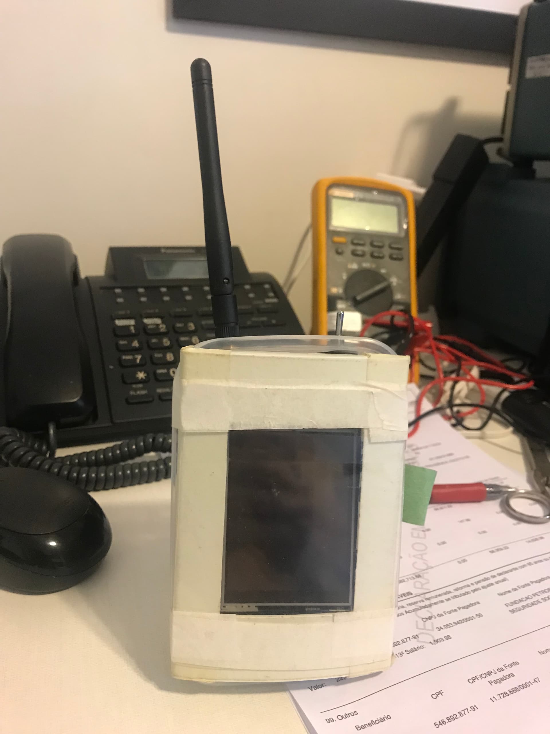
I have a duplicate harware assembly of the receptor that is used in the existing installation that I use for testing new implementations of code.
here are some photos of it.


OBS. I checked the existing hardware and for now there are 3 extra pins free.
Unfornunately this option will cause the addition of so many jumper wires and trace cuts to render the existing pcb unusable.
I will have to order some more with the new design. The main issue with this is that I depend on a 3rd party to manufacture them since I am not familiar with schematics/pcb design software.
Another working solution that solved the conflict with the SDcard library was to use the spi.begintransaction() and spi.endtransaction() instruction at the begin and end of each call to devices that uses the SPI bus.
Unfortunately I could find the correct parameters to try this solution.
Can anyone help me on that?
Thank you
is the SD card something you recently added? I cannot see it in your circuit schematic in post 9
if the SD card is sharing a SPI bus with other devices there can be problems - see Sharing the SPI bus among SD card and other SPI devices
EDIT: is the SD card part of the display module or a separate module?
you could be overloading the ESP32 3.3V power???
SD-card, this is the first mention of an SD card.
the display in post how-to-store-a-word-from-serial-monitor looks similar to yours
@PaulRB makes some interesting comments regarding problems with this type of display
Dear all,
No, I do not have an SD card on the system, but I was using this as an example of a SPI problem that was solved using spibegingtransaction() / spiendtransaction() that might be useful in this case.
I am sorry for the confusion.
Ok that's clear. hmm but still no solution.
Could you show me one from the side ? The NF24 antenna does look rather close to the ESP32. Shouldn't affect the init, but it may affect it's workings.
It should.
Should be the way to go though. That avoids direct conflicts.
Kicad is not that hard to learn. If you try it out on the extra hardware, at least you can confirm it works. I think it won't be that hard to expose the extra pins, but if you really are going to redesign the PCB, put the antennas further apart ! Also maybe you could share the current schematic of the shield with us, because i am a little suspicious of the power rails and regulator heatsink. What are you using for a PSU to power the whole thing ?
receiver: TFT and NRF24 connected to ESP32 as your circuit schematic in post 9
// ESP32 TFTESP32: TFT & NRF24 on VSPI
// https://github.com/Bodmer/TFT_eSPI/tree/master
// in file TFT_eSPI/User_Setup_Select.h the following is defined
// #include <User_Setups/Setup42_ILI9341_ESP32.h> // Setup file for ESP32 and SPI ILI9341 240x320
// in file TFT_eSPI/User_Setups/Setup42_ILI9341_ESP32.h the following is defined
// #define ILI9341_DRIVER
//
// #define TFT_MISO 19 // (leave TFT SDO disconnected if other SPI devices share MISO)
// #define TFT_MOSI 23
// #define TFT_SCLK 18
// #define TFT_CS 15 // Chip select control pin
// #define TFT_DC 2 // Data Command control pin
// #define TFT_RST 4 // Reset pin (could connect to RST pin)
// TFT VCC and LED to 3.3V
#include <SPI.h>
#include <TFT_eSPI.h> // Hardware-specific library
TFT_eSPI tft = TFT_eSPI(); // Invoke custom library
#include <SPI.h>
#include <RF24.h>
bool radioNumber = 1;
const uint8_t pipes[][6] = { "1Node", "2Node" };
#define CSN_PIN 16 // for NRF24L01
#define CE_PIN 17
RF24 radio(CE_PIN, CSN_PIN); //400000); // NRF24L01 constructor
char dataReceived[10]; // this must match dataToSend in the TX
bool newData = false;
void setup(void) {
Serial.begin(115200);
delay(2000);
Serial.println("ESP32: TFT & NRF24 on VSPI");
// initialise NRF44L01 before TFT
Serial.println("ESP32 NRF24L01 VSPI initialise");
radio.begin(); // initialise NRF24L01
if (radio.isChipConnected()) {
Serial.println("NF24L01 connected to SPI");
//tft.println("NF24L01 connected to SPI");
} else {
Serial.println("NF24 is NOT connected to SPI");
//tft.println("NF24 is NOT connected to SPI");
while (1)
;
}
radio.setChannel(125);
radio.setDataRate(RF24_1MBPS);
//radio.setDataRate(RF24_250KBPS);
radio.printDetails();
if (!radioNumber) {
radio.openWritingPipe(pipes[0]);
radio.openReadingPipe(1, pipes[1]);
} else {
radio.openWritingPipe(pipes[1]);
radio.openReadingPipe(1, pipes[0]);
}
radio.startListening();
// initialise TFT screen
Serial.println("ESP32 TFT VSPI initialise");
tft.init();
tft.setRotation(1);
tft.fillScreen(TFT_BLACK);
tft.setTextFont(4);
//Set the font colour to be white with a black background
tft.setTextColor(TFT_WHITE, TFT_BLACK);
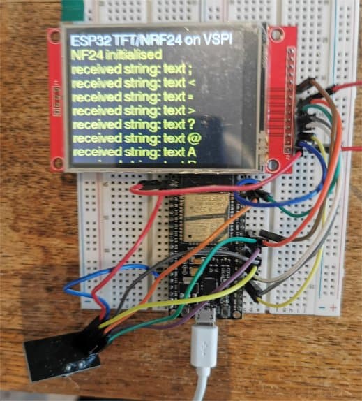
tft.println("ESP32 TFT/NRF24 on VSPI");
tft.setTextColor(TFT_YELLOW, TFT_BLACK);
// radio.setPayloadSize(sizeof(Struct1));
tft.println("NF24 initialised");
}
void loop() {
if (radio.available()) {
char testString[10] = "";
radio.read(testString, sizeof(testString));
Serial.print("received string: ");
Serial.println(testString);
tft.print("received string: ");
tft.println(testString);
}
}
ESP serial monitor output
ESP32: TFT & NRF24 on VSPI
ESP32 NRF24L01 VSPI initialise
NF24L01 connected to SPI
SPI Speedz	= 10 Mhz
STATUS		= 0x0e RX_DR=0 TX_DS=0 MAX_RT=0 RX_P_NO=7 TX_FULL=0
RX_ADDR_P0-1	= 0x65646f4e32 0x65646f4e31
RX_ADDR_P2-5	= 0xc3 0xc4 0xc5 0xc6
TX_ADDR		= 0x65646f4e32
RX_PW_P0-6	= 0x20 0x20 0x20 0x20 0x20 0x20
EN_AA		= 0x3f
EN_RXADDR	= 0x03
RF_CH		= 0x7d
RF_SETUP	= 0x07
CONFIG		= 0x0e
DYNPD/FEATURE	= 0x00 0x00
Data Rate	= 1 MBPS
Model		= nRF24L01+
CRC Length	= 16 bits
PA Power	= PA_MAX
ARC		= 0
ESP32 TFT VSPI initialise
received string: text ;
received string: text <
received string: text =
received string: text >
received string: text ?
received string: text @
received string: text A
received string: text B
received string: text C
received string: text D
received string: text E
received string: text F
received string: text G
received string: text H
photo
the transmitter is a ESP8266 with NRF24L01
//  ESP32 > NRF24L01 transmitter test using a text string

// RP2040 connections
// RP2040 SPIO_SCK pin GP18 goes to NRF24L10_pin SCK
// RP2040 SPIO_RX pin GP16 goes to NRF24L10_pin MISO
// RP2040 SPIO_TX pin GP19 goes to NRF24L10_pin MOSI
// RP2040 pin SPIO_CSn GP17 to NRF24L10 CSN
// RP2040 pin GP20 to NRF24L10 CE
// RP2040 GND and 3.3V to NRF24L10  GND and VCC

// Leonardo connections ???
// Leonardo ICSP SCK  pin 15 to NRF24L10_pin SCK
// Leonardo ICSP MISO pin 14 to NRF24L10_pin MISO
// Leonardo ICSP MOSI pin 16 to NRF24L10_pin MOSI
// Leonardo pin 10 to NRF24L10 CSN
// Leonardo pin 9  to NRF24L10 CE
// Leonardo GND and 3.3V to NRF24L10  GND and VCC

// ESP8266 connections
// ESP8266 SCK pin GPIO14 goes to NRF24L10_pin SCK
// ESP8266 MISO pin GPIO12 goes to NRF24L10_pin MI
// ESP8266 MOSI pin GPIO13 goes to NRF24L10_pin MO
// NRF24L10 CE to ESP8266 pin GPIO4
// NRF24L10 CSN to ESP8266 pin GPIO5

#include <SPI.h>
#include "RF24.h"

#define CE_PIN 4
#define CSN_PIN 5

bool radioNumber = 0;
RF24 radio(CE_PIN, CSN_PIN);

byte addresses[][6] = { "1Node", "2Node" };

void setup() {
  Serial.begin(115200);
  delay(2000);
  Serial.println("\n\nESP8266 > NRF24L01 transmit text");
  radio.begin();
  if (radio.isChipConnected())
    Serial.println("Transmitter NF24 connected to SPI");
  else {
    Serial.println("NF24 is NOT connected to SPI");
    while (1)
      ;
  }
  radio.setChannel(125);
  radio.setPALevel(RF24_PA_MIN);
  radio.powerUp();
  radio.setDataRate(RF24_1MBPS);
  //radio.setDataRate(RF24_250KBPS);
  if (radioNumber) {
    radio.openWritingPipe(addresses[1]);
    radio.openReadingPipe(1, addresses[0]);
  } else {
    radio.openWritingPipe(addresses[0]);
    radio.openReadingPipe(1, addresses[1]);
  }
  radio.stopListening();
  //radio.setPayloadSize(sizeof(Struct1));
}

// loop transmiting data packet
void loop() {
  static char testString[10] = "text 0";
  radio.write(testString, sizeof(testString));
  Serial.print("transmit ");
  Serial.println(testString);
  delay(1000);
  testString[5]++;
}
serial monitor output
ESP8266 > NRF24L01 transmit text
Transmitter NF24 connected to SPI
transmit text 0
transmit text 1
transmit text 2
transmit text 3
transmit text 4
transmit text 5
transmit text 6
transmit text 7
transmit text 8
transmit text 9
transmit text :
transmit text ;
transmit text <
transmit text >
transmit text ?
transmit text @
transmit text A
transmit text B
Thanks Horace and Deva_rishi for your replies.
It seems the fault is obvious by now... hardware fail...
I am ashamed of not trying this at first... but there is a small probability of the problem being caused by a revision on the board file.
I came across of people downgrading their board files while googling for solutions to this issue
I will do it as soon as I can and post the results here.
Concerning the schematics, it is shown in post # 9.
The power comes from a external 5V power block and is regulated to 3.3V by a LD1117.
I had to pack the PCB's/modules as close as possible so the can be mounted inside a 4cmx 2cm wall receptacle.
Here is a photo of the prototipe used for testing
Hi,
I replaced the ESP32 Dev kit V1 on my set and the problem is still happening.
Now I am testing the downgrade of board files to the latest 2.n.n.n revison.
I read that there important changes in pin assignment from rev 2.n.n.n to 3.n.n.n. including USB0, which might explain why my serial monitor keeps printing garbage.
Note: The board file downgrade to version 2.0.17 did not work.
Serial monitor is still printing garbage, and radio not found.
My next test will be return to the latest board file and try Horace code.
I will return as soon as have new information.
Horace, would you please inform what is the board file version you have intalled on your computer?
Thank you
I am
Than you.
I use Tools>Board "ESP32 Dev Module" - ESP32 core version is 3.0.6
what other devices as well as the TFT and NRF24L01 do you have connected?
Thank you Horace.
I think I am getting closer.
I uninstalled/reinstalled Arduino IDE and now I am getting the following compilation errors, which are related to the SPI bus.
What should I do?
      |        ^~~~~~~
In file included from H:\Arduino\SketchBook\libraries\TFT_eSPI\TFT_eSPI.cpp:24:
H:\Arduino\SketchBook\libraries\TFT_eSPI\Processors/TFT_eSPI_ESP32.c: In member function 'bool TFT_eSPI::initDMA(bool)':
H:\Arduino\SketchBook\libraries\TFT_eSPI\Processors/TFT_eSPI_ESP32.c:805:3: warning: missing initializer for member 'spi_bus_config_t::data4_io_num' [-Wmissing-field-initializers]
  805 |   };
      |   ^
H:\Arduino\SketchBook\libraries\TFT_eSPI\Processors/TFT_eSPI_ESP32.c:805:3: warning: missing initializer for member 'spi_bus_config_t::data5_io_num' [-Wmissing-field-initializers]
H:\Arduino\SketchBook\libraries\TFT_eSPI\Processors/TFT_eSPI_ESP32.c:805:3: warning: missing initializer for member 'spi_bus_config_t::data6_io_num' [-Wmissing-field-initializers]
H:\Arduino\SketchBook\libraries\TFT_eSPI\Processors/TFT_eSPI_ESP32.c:805:3: warning: missing initializer for member 'spi_bus_config_t::data7_io_num' [-Wmissing-field-initializers]
H:\Arduino\SketchBook\libraries\TFT_eSPI\Processors/TFT_eSPI_ESP32.c:805:3: warning: missing initializer for member 'spi_bus_config_t::isr_cpu_id' [-Wmissing-field-initializers]
H:\Arduino\SketchBook\libraries\TFT_eSPI\Processors/TFT_eSPI_ESP32.c:829:3: warning: missing initializer for member 'spi_device_interface_config_t::clock_source' [-Wmissing-field-initializers]
  829 |   };
      |   ^
Hi @rogerio414.
It is important to understand the difference between warnings and errors. A warning is the compiler telling you there is something in the code that could possibly cause a problem, but doesn't cause the compilation to fail. An error is a problem with the code that causes compilation to fail. In this case you have posted warnings, not errors. In order to avoid confusion, we should be careful to use the appropriate terminology when communicating about technical subjects.
The output will show warnings that come from any of the code being compiled, which includes the "core" that defines the standard Arduino language API for the board as well as any libraries being used by your sketch.
You should pay attention to warnings and fix them in your own code whenever possible. Unfortunately some core and library authors don't hold themselves to such high standards so sometimes you do just need to ignore a warning that is produced by code you didn't write. That can be quite annoying since you must sort though the warnings from other people's sloppy code to make sure none are coming from your own code.
Thanks you all for the replies.
I am really lost!!!
Here are my last attempts to try to isolate the problem.
1 - I reinstalled the TFT_eSPI library and edited the user_setup_select and user_setup files
2 - Uploaded the Read user setup example from Bodmers' library
the serial monitor worked perfect and I got this:
[code]
TFT_eSPI ver = 2.5.43
Processor    = ESP32
Frequency    = 240MHz
Transactions = Yes
Interface    = SPI
Display driver = 9341
Display width  = 240
Display height = 320

MOSI    = GPIO 23
MISO    = GPIO 19
SCK     = GPIO 18
TFT_CS   = GPIO 15
TFT_DC   = GPIO 2
TFT_RST  = GPIO 4

Font GLCD   loaded
Font 2      loaded
Font 4      loaded
Font 6      loaded
Font 7      loaded
Font 8      loaded
Smooth font enabled

Display SPI frequency = 40.00
[/code]
3- Uploaded the TFT_readwrite_test example
The serial monitor works, but returns only READ ERRORS!
All the read values were equal to 0
4- Uploaded the DMA TEST/boing_ball example
the displays worked fine !!
How is it possible if I could not read the pixel values?
5- Uploaded the Horace code for my existing pinout
NOTE: I have changed the connection of nRF24L01 CS pin to GPIO 5 (who knows?.....)
NO DISPLAY
NO SERIAL MONITOR OUTPUT
6- Uploaded 320X240/ TFT_Graphictest_PQD
All graphics worked
Test values are PRINTED ON SERIAL MONITOR !!!
I have no ideas on how to move on.
ANY suggestion is welcome.
Thanks
Does the problem still occur if you disconnect everything other than the display from the ESP32 board and try again with this sketch?
Are you referring to the code from post #33?
Have you tried your original project sketch to see if it is working now? Using the library examples to test the basic functionality of each component is absolutely the right approach. However, you should always consider the possibility that there is a bug in the example in the case where an example doesn't work as expected (for example, the example might have worked when it was written, but then was not updated at a later time when the developers made a change to the library code that broke the example).