Esp32 with solenoid door for blynk

Hi, I want to control Door Lock/Unlock from Blynk App. But whenever I connect my project, the relay will auto switch on and the solenoid door stay unlocked.

Problem:

  1. The relay will always on and solenoid door stay unlocked.
  2. The PIR Motion sensor always detect motion, ( but I do not really mind it because I just want it to show notification and then I will put delay for 30 mins for the demo notifications pop-up, but would appreciate anyone help to set pir motion sensor to detect properly)

Objective:
I want to control the solenoid door lock from phone via button, and when there is motion detected, a notification should appear from Blynk app.

Components:
ESP-WROOM-32
SELENOID DOORLOCK 12V
5V RELAY MODULE
PIR MOTION SENSOR

I follow this circuit wiring:


And this is my code:

#define BLYNK_PRINT Serial

/* Fill in information from Blynk Device Info here */
#define BLYNK_TEMPLATE_ID ""
#define BLYNK_TEMPLATE_NAME "smart door"
#define BLYNK_AUTH_TOKEN ""

#include <WiFi.h>
#include <BlynkSimpleEsp32.h>

// Wi-Fi credentials
char ssid[] = "";
char pass[] = ";

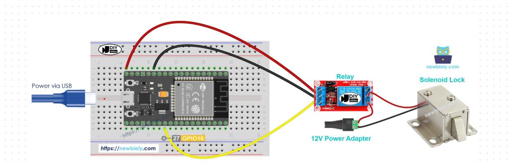
const int RELAY_PIN = 16; // GPIO16 for the relay
const int PIR_PIN = 13;   // GPIO13 for the PIR motion sensor

bool isLocked = true; // Initial lock state
BlynkTimer timer;     // Use Blynk's non-blocking timer

// Function to check motion and send notification
void checkMotion() {
  int pirState = digitalRead(PIR_PIN);
  Blynk.virtualWrite(V0, pirState); // Send PIR state to Virtual Pin V0

  if (pirState == HIGH) {
    Serial.println("Motion detected!");
    Blynk.logEvent("detectMotion", "Motion Detected Near the Door!");
  }
}

BLYNK_WRITE(V1) { // Virtual pin V1 for lock control
  int lockState = param.asInt(); // Get the value from the app (0 or 1)
  
  if (lockState == 1) {
    digitalWrite(RELAY_PIN, HIGH); // Unlock the door (Relay OFF)
    Serial.println("Door Unlocked");
    isLocked = false;
  } else {
    digitalWrite(RELAY_PIN, LOW); // Lock the door (Relay ON)
    Serial.println("Door Locked");
    isLocked = true;
  }
}

void setup() {
  Serial.begin(115200);
  delay(10);

  // Configure GPIO pins
  pinMode(RELAY_PIN, OUTPUT);
  pinMode(PIR_PIN, INPUT);

  // Default state: Door locked (Relay ON)
  digitalWrite(RELAY_PIN, LOW);
  isLocked = true;
  Serial.println("System Initialized: Door is Locked");

  // Connect to Wi-Fi
  Serial.print("Connecting to ");
  Serial.println(ssid);
  WiFi.begin(ssid, pass);

  while (WiFi.status() != WL_CONNECTED) {
    delay(500);
    Serial.print(".");
  }
  Serial.println("\nWiFi Connected");

  // Initialize Blynk
  Blynk.begin(BLYNK_AUTH_TOKEN, ssid, pass);

  // Set up the motion check function to run every second
  timer.setInterval(1000L, checkMotion);
}

void loop() {
  Blynk.run();
  timer.run(); // Run BlynkTimer
}

Really appreciate helps. Thankyou!

Update: i tried changing wiring from 5V to 3V3, the relay switch can be controlled but the not strong enough for solenoid lock. What can i do?

What does the datasheet for the relay look like?

1 Like

do you mean this?

https://www.alldatasheet.com/datasheet-pdf/view/1131944/SONGLERELAY/SRD05VDCSLC.html

Yes. Thanks.
You've got the 5 volt version. Then use 5 volt, not 3.3 volt.

1 Like

yes, i did use 5V for my relay. But the switch (green led) wont turn off, it just stays on. So my door stay unlocked.

Which pins on the relay output side did You use? It sounds like You used C an NC. Use C and NO.

1 Like

Do you mean C (middle) to the power source? And NO to the selenoid, right? or is it otherwise, sorry i got confused

update: i tried C for the power source, NO for solenoid

Now, the solenoid is locked until reset. But still, the relay is always on

Can't tell. The picture doesn't show the names of the pins.

Maybe Your code is wrong. Writing a HIGH will activate the lock. Swap HIGH to LOW and vice versa.

Real schematics could help. Also posting a link to the final page of the datasheet too.

1 Like

Hi, im not sure how to do schematic diagram, I have seen example but i dont really have much time to learn schematic diagram, i am so sorry….

but this is just my real pin diagram i tried to make it out as clear as possible……

Thankyouu a lot, im sorry if this is very lacking pls do tell me i will try to provide as much information as i can.

(I did not use any transitor, resistor, diodes etc)

——

For code, I have tried adjust HIGH and LOW, still just static unless resetting

This is my first class of doing this, I have no knowledge about electrical circuit or related prior to this….

hii, sooo i think i might know what I am missing. So i just want confirmation….

is it because im using esp32 which i read from google, says can only run 3.3~3.6V despite having V5 pin?

Very bad idea, since that would apply 5V to your ESP 3.3V GPIOs which is not good. It could damage your ESP.

1 Like

That is an excellent diagram.
Do you have any transistors?

1 Like

Do you have any transistors?

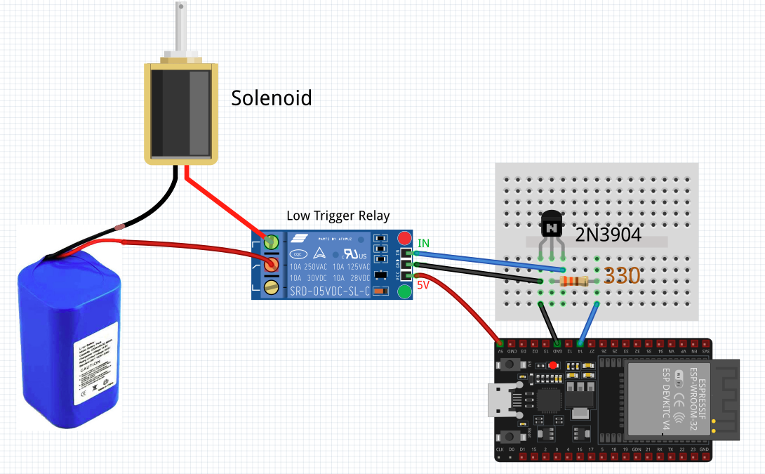
unfortunately, for now i did not add any transistors. But if necessary, i will add. I thought this will be simple project just like Youtube and Google show but I got lost haha…

This is the tutorial i followed, but I guess it might be because of different type of 5V relay module:
https://esp32io.com/tutorials/esp32-solenoid-lock

So, should I change VCC to 3V3 pin and add something to make it able to control 5V relay module, instead of direct 5V pin?

Like this

No, they don't claim that it works nor do they actually show working. It's one of those site where they get money if you buy the parts in the links.

thanks a lot for your information and advices, really appreciate the circuit diagram you provided :smile:

But, I have found a solution for this, and it worked well now :grin:

i see, well that makes sense :slightly_smiling_face:‍:arrow_up_down:

Glad you solved the problem?
Have a nice day?

1 Like

Update: i have found the solution which is, i added a green LED with anode to the "IN" pin and cathode it to the 3.3V ESP32. Well, i am not good at explaining the logic behind, but it works :smile: and if anyone having the same problem, maybe these schematic would help you:

Some explanations from another user:

Adding that will drops 2V so when

  1. ESP32 output is LOW at 0V, the relay module will see 3V and turned on.
  2. When the ESP32 output is HIGH at 3.3 V, there will be insufficient voltage across the LED for it to light and the relay module will be off.

Thanks to @Paul_B, for explaining it and pointing it out to me :smile:

————-

Also, thanks a lot to everyone who spend their time to respond to this post, i did learnt a lot just from this post!

yes, have a nice day!! thankyou for taking your time to explain these to me too :smile:

may your days always be blessed!