ESP8266 (ESP-01) Issue - help needed ASAP

I've spent the past 2 hours trying to get my ESP8266 working and I'm just stuck; I'm working on a project where I need to log data from a gas sensor and a DHT sensor to a Firebase rtdb using ESP8266 btut my issue is I can’t get the ESP8266 to respond at all

Wiring:

  • ESP8266 GND → Common ground
  • ESP8266 3V3 → Arduino 3.3V
  • ESP8266 RX → Voltage divider (2 x 1kΩ resistors: one from Arduino TX (pin 11) to RX, the other from RX to GND)
  • ESP8266 TX → Arduino pin 11

& I’m using this code to test w/ SoftwareSerial:

#include <SoftwareSerial.h>

#define ESP_RX 10
#define ESP_TX 11 

SoftwareSerial espSerial(ESP_RX, ESP_TX);

void setup() {
  Serial.begin(9600);
  espSerial.begin(9600);  // ESP-01 default baud rate
  Serial.println("Testing Arduino and ESP-01 communication...");
}

void loop() {
  if (espSerial.available()) {
    char c = espSerial.read();
    Serial.write(c);
  }

  if (Serial.available()) {
    char c = Serial.read();
    espSerial.write(c);
  }
}

when I open the serial monitor, it just prints the initial line and then nothing no response from the ESP8266 at all

I tried swapping TX/RX, tried different baud rates, still nothing.

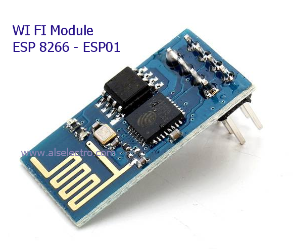
I have to finish this by TOMORROW and I rly need help. Is my wiring wrong? Is the Arduino’s 3.3V not giving enough current? Should I use a separate 3.3V power source? I’m using an Arduino Uno and an ESP-8266. (image attached)

Thanks in advance :folded_hands:

The Uno's 3.3volt/150mA can supply the ESP8266's steady current of ~100mA, but not the ~400mA peak currents during WiFi trafic. A 470uF buffer capacitor on the 3.3volt line can help with that. That said, an ESP01 power adapter board, powered from 5volt could be a safer solution.
But why the Micky Mouse solution of an Uno and ESP combo.
A single ESP(32) board with enough I/O could replace both.
Leo..

Not impressive. Personally spent one hole year, redesigning the memory, nothing helped until in the middle of the night the thought came up, a hardware choice made 3 years ago!

Present it as full schematics. Lyrics is not precise enough.

Then You are in deep trouble, using but not understanding what the code is made to do, and how.

Impulsive random wild guesses tell other things than You want.

How would this help forum understand what's wrong?

Datasheet and schematics are needed.

Datasheet had been better.

Sorry....

The whole project has to run on Arduino as per the project requirements,

Won't that fry the module? Correct me if I'm wrong just asking

It's the first time I use any type of wifi module, so I apologize for my lack of knowledge on this, however I then realized that the module wasn't even getting enough current to power on since the 3.3v pin on the Arduino Uno only supplies it with 100mA, which is not enough

An ESP-01 adapter board has a dedicated voltage regulator to turn 5volt into 3.3volt.
But try a 470uF capacitor on the Uno's 3.3volt line first.
Leo..

Assuming you have the voltage divider correctly (Arduino Tx -> 1k -> Esp Rx -> 1k -> 1K -> GND)

Have loaded any other firmware onto the ESP instead of the original AT-command firmware (assuming that it had it on it, which is not a guarantee) ?

Have you really connected both pins to Arduino pin 11 ? (i suspect not, but that is what it says)

I have always powered my ESP-01 with the 3.3v pin from my (original) UNO and i have had no issue with that, but not all UNO boards are the same. That said, the peak power demands occur during WiFi connection, which for this simple test is not applicable.

The 3.3v probably should suffice. Also do you really have a unit with blue PCB or is it black ?

So anyway, about your code.

The ESP default baud rate for most AT-commands firmware is 115200. Also you are assuming that the ESP will just respond to whatever you send to it, but that is not really true (other then a possible '?' )

So let's do this step by step (as i still haven't finished my tutorial)

Step 1 :
We will simply use the UNO as both a 3.3v power supply and as a USB to TTL bridge. for that we need to upload an empty sketch (or blink or at least something that doesn't use pins 0 & 1 and / or Serial) onto the UNO.
Then we can let the ESP take the place of the UNO mcu by connecting it's TX & RX pins to the UNO TX & RX pins.
So the wiring would be
UNO ESP
3.3v Vcc
GND GND
TX TX
RX->1K->RX->1K->1K->GND

Now open the Serial monitor and modify it's settings to

  • Baud-rate to 115200
  • Line ending to BOTH CR & NL

Now type 'AT" in the Serial monitor and press enter and if there is AT-commands firmware on the ESP, it should respond. Next step is after this one has been successfully completed.

That is true, but in fact almost any ESP will have enough pins.
The ESP-01 has 4 pins, and if you do not use Serial to communicate with anything, they can all be used as a GPIO pin. The DHT sensor only needs 1 pin, and the gas sensor was not specified, but will probably not require more than 2 pins.

Oh and silly bugger me. CP_PD should also be connected to 3.3v !!
or nothing will work at all.
So the wiring would be
UNO ESP
3.3v Vcc
3.3v CH_PD
GND GND
TX TX
RX->1K->RX->1K->1K->GND

probably a good thing because

That could and probably would have damaged the TX pin had the ESP been enabled.
n.b. avoid using pins 11 & 12 on an Arduino for swSerial communication. Apparently they go through a HIGH-LOW cycle at boot and this can cause damage to the other device.

And 115200 might be too high for Uno software serial...

It can transmit at that speed reliably enough, but reception is not reliable. When using AT-commands, the strategy is to first send the AT command to switch to 9600, and then switch swSerial to that.

1 Like

are you using espsoftwareserial?

Did you read the whole original post ?

yes, did not see any mention of the EspSoftwareSerial library which is a Implementation of the Arduino software serial for ESP8266/ESP32
thought it worth checking

Well it would if the ESP would be the processor doing the swSerial thing, but it's not. An UNO is used to connect to an ESP-01 (which would typically use hwSerial it self, i can not think why one would use swSerial on an ESP-01 ? )
There is a Library which provides a class to control the ESP through it's UART and (oh ? what do you call that) let's you call member functions from another processor and it will appear as if the ESP is like an ethernet/WiFi shield. The library is maintained by one of the Forum members (@Juraj ?!) It has some requirements for the AT-command firmware if i am correct, but it would be a thing to consider once has been established the ESP still works and has AT-command firmware on it.

This topic was automatically closed 180 days after the last reply. New replies are no longer allowed.