I'm using an Arduino as a valve controller for this pneumatic shifting system I'm making, and the operation is pretty simple, power is sent to the valve through an N-fet, and a signal is sent from an Arduino pin to the gate.
I noticed that when I used a 18ohm resistor, the valve would stutter a lot, then when I kept using bigger resistors, eventually moving to 2.2K, the circuit functioned as intended. Can someone explain to me physically why this is? I also noticed that the voltage across the drain and source didn't take as much time to ramp up and ramp down.
I'm trying to set this system up so I press a button on the wheel and it shifts, so on my test bench (if you could even call it that), I have one wire coming out of 5V on the arduino and one coming out of a digital pin so touching them together simulates a SPST switch. whithout any resistance, the valve just stuttered and nothing worked correctly, when I put a resistance of 18K ohm in line with the two wires, there still was some stuttering. So my second question is am I doing this right and just have to use a really high resistance between the 5V and signal pins?
I've got the arduino and Drain/Source lines connected to a car battery for power.
Sorry if the post was hard to follow, and I'm pretty new at making my own circuits so if I sound completely ignorant it's because I am.
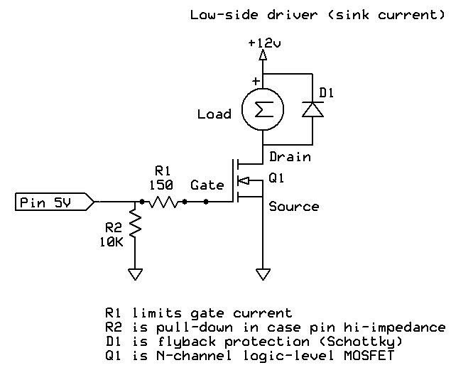
Anyway, I attached a diagram.
Is the lack of a flyback diode what's causing the stuttering? would that also explain why I was getting voltages across the drain and source that weren't
I have one wire coming out of 5V on the arduino and one coming out of a digital pin so touching them together simulates a SPST switch.
The stuttering may be switch bounce. As you touch the wire they will make and break several times before contact is solid. Look up switch debouncing. And you need a pull up resistor from pin 2 to Vcc.
Without a free wheel diode you may be destroying your MOSFET - all depends how rugged it
is. The gate-drain capacitance will link that pulse back to the gate and if there is a low
value resistor on the gate that pulse will go back to the Arduino and possibly fry it.
Always use a free-wheel diode or other snubber circuit when switching an inductive load,
inductors can easily blow up your semiconductors otherwise.
Diode must be rated for the supply voltage, the load current, and be connected backwards
across the inductor. When you switch off the current the inductor will absolutely not let it
stop instantly, but fortunately the diode forms an easy route for the current to dissipate in.
Think of trying to stop a train with a brick wall, or alternatively just switching the points
and letting it go down a different bit of track - the latter is far less destructive!
Are you using an arduino to control the mosfet? I did not see the arduino in the diagram .
What MOSFET are you using (URL would be a help). Is it logic level?
For test, forget the switch, use the blink example code, and drive the MOSFET. That should give a clean (no bounce) signal. How did that look?
I'm surprised you get stuttering with that circuit, unless you are trying to control the valve position using PWM (i.e. you are using the analogWrite function instead of the digitalWrite function ). Are you? If so, then adding the flyback diode should reduce the stuttering, but you may need to increase the PWM frequency in order to eliminate it.
I have one wire coming out of 5V on the arduino and one coming out of a digital pin so touching them together simulates a SPST switch.
That is probably where the "stuttering" is coming from.
If he tries driving it from the "blink script" and still gets stuttering, then we should look elsewhere for the source.
Looking at his diagrams again, I see that he has connected his input to +5V via a switch, but has not used a pulldown resistor. So the input will be floating when the switch is not pressed.
Not using a common ground coupled with the lack of a flyback diode is what was giving me the strange stuttering, and the weird capacitance is from not grounding the gate signal. So the that's all working fine now.
The problem I had with the switch was that I didn't use a reference ground, I made the pin active low and everything is working.