Fading a LED In and out, with duration variables

I have a code that fades an LED in and out. Defined are variables to adjust the min/max brightness and fade Increment. So far everything works. I am trying to add two new variables to define a duration to hold at max brightness and to hold again at min brightness... of course without using Delay().

The code is integrated in a much larger script, so I am posting only the most relevant parts:

Definitions:

// define directions for LED fade
#define UP 0
#define DOWN 1

Constants:

const byte pwmLED = 11;            //  Requires a PWM pin. 
const int minPWM = 0;              // Limit for min PWM
const int maxPWM = 255;            // Limit for max PWM
byte fadeIncrement = 5;            // Smoothness of fade transition
const int minPWMduration = 5000;   //Once the min value is reached, remain for this duration
const int maxPWMduration = 1000;   //Once the max value is reached, remain for this duration
byte fadeDirection = UP;           // Variable for Fade Direction
int fadeValue = 0;                 // Global Fade Value - bigger than byte and signed, for rollover

Statement in void setup:

 analogWrite(pwmLED, fadeValue);  // put pwmLED into known state (off)

Statement in void loop:

 FadeLED(currentMillis);  

The function that is called out:


void FadeLED(unsigned long currentMillis) {
   // is it time to update yet? if not, nothing happens
   
   if (currentMillis- previousFadeMillis >= fadeInterval) {
      // Going UP
      if (fadeDirection == UP) {
         fadeValue = fadeValue + fadeIncrement;
         if (fadeValue >= maxPWM) {
                      //***************************************************************
                      //        AnalogWrite does not go to full brightness            * 
                      //***************************************************************                                                              
             if (maxPWM == 255) {digitalWrite(pwmLED, HIGH); // Turn LED at full bright if a PWM value of 255 is needed  
                        
              if(millis() <= currentMillis+ maxPWMduration){  //wait the ON duration       
              fadeValue = maxPWM;    // At max, limit and change direction
              fadeDirection = DOWN;
              }
            }            
         }
      } else {
         // Going DOWN
         fadeValue = fadeValue - fadeIncrement;
         if (fadeValue <= minPWM) { 
                      //***************************************************************
                      //  AnalogWrite minimums out at a brightness of about 3 (NOT 0) * 
                      //***************************************************************  
             if (minPWM == 0) {digitalWrite(pwmLED, LOW); // Turn LED off if a PWM value of 0 is needed  

              if(millis() <= currentMillis + minPWMduration){  //wait the OFF Duration
              fadeValue = minPWM;      // At min, limit and change direction
              fadeDirection = UP;
              }
            }            
         }
      }
      // Only need to update when it changes
     // analogWrite(pwmLED, fadeValue);  // executed in Switch LEDs Function above
     
      previousFadeMillis = currentMillis;    // reset millis for the next iteration (fade timer only)
   }
}

The min and max durations (minPWMduration & maxPWMduration) are nested in an IF, everything compiles successfully, but there is no delay at either brightness level.

I tested this with a WHILE statement just to see if the idea in general was sound, and it worked fine, so I am guessing I simply have set up my IF incorrectly, but I do not see what I am doing wrong. I would be grateful for any hints as to how to correct this.
don't you need a state or modes for increasing, holding the max, decreasing and holding the min?

what you want to do sounds like a perfect application for a finite state machine

The system will be in one of 4 states at any one time

FADING_UP
HOLD_AT_MAX
FADING_DOWN
HOLD_AT_MIN

The neatest way to implement this would be by using switch/case to execute the code for the current state, then switch to the next one at the appropriate time

You could do this using if/else if/else but switch case produces more readable code in my opinion

Use a variable to hold the current state then switch the code executed using that value for the current case

2 Likes

My idea was to simply delay it using millis() once the min or max values are reached. It worked well enough with WHILE, but of course that blocked the rest of the code while it was waiting.

while (millis() <= currentMillis + maxPWMduration){}

You would use millis() for timing but no while loop in each of my suggested states thus not blocking the rest of the code

Each time the code for the current state is executed it checks whether it is time to do something. The fading states would change the brightness of the LED when the correct time had passed and once the brightness reached the end value would switch to the appropriate hold state. In those states when the state code was executed next it would check whether the hold period had passed and switch to the appropriate fading state

Remember, only one state would be active at any one time

1 Like

Ok, I am going to have to read up on that and play with it for a while. Thanks for the tip. :slight_smile:

Possibly instructive:

1 Like

if there is a direction vairable, and a timer period variable, msecPeriod, direction can be toggled when the max/min is reached and msecPeriod set to MaxDuration/MinDuration while msecPeriod is normally set to the fade period

I'd encapsulate the state machine, control, timing, etc into a simple class like the one @dougp linked. Then all you'd have to do is call an update() function on every iteration of your loop() function.

look this over - corrected

const byte PinLed       = 11;

const int  MinPwm       =    0;
const int  MaxPwm       =  255;
int        fadeInc      =    5;

const int  MinPwmPeriod = 5000;
const int  MaxPwmPeriod = 1000;
const int  PwmPeriod    =   50;

int   fadePwm       = MinPwm;

unsigned long fadePeriod = PwmPeriod;
unsigned long msecFade;

// -------------------------------------
void fade (
    unsigned long msec )
{
    if (msec - msecFade < fadePeriod)
    return;

    msecFade += fadePeriod;

    fadePwm += fadeInc;
    analogWrite (PinLed, fadePwm);


    if (MinPwm == fadePwm)  {
        fadeInc = -fadeInc;
        fadePeriod = MinPwmPeriod;
        Serial.println (fadePwm);
    }
    else if (MaxPwm == fadePwm)  {
        fadeInc = -fadeInc;
        fadePeriod = MaxPwmPeriod;
        Serial.println (fadePwm);
    }
    else
    fadePeriod = PwmPeriod;
}


// -----------------------------------------------------------------------------
void
loop (void)
{
    unsigned long msec = millis ();

    fade (msec);
}

void
setup (void)
{
    Serial.begin (115200);
    pinMode (PinLed, OUTPUT);
}
1 Like

AD9833_ADSR waveform generator.

UP isn't defined in what you posted. If wherever you defined UP you added values for names like:

...you could change your code to handle:

      if (fadeDirection == UP  || fadeDirection == FADING_UP) {
         ...
      } else if (fadeDirection == HOLD_AT_MAX) {
         ...
      } else if (fadeDirection == FADING_DOWN) {
         ...
      } else if (fadeDirection == HOLD_AT_MIN) {
         ...
      }

...then you have the skeleton of a Finite State machine to fill in the other behaviors like you already know how to do.

1 Like

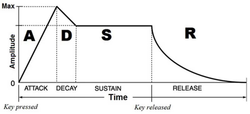
Or... make your own ADSR envelope. Still needs to be mapped to the LED and buzzer.

sketch.ino
/*
           /\
          / ^\ DECAY
  ATTACK /  | \_____________
        /   |     SUSTAIN   \
       /    |VOLUME          \ RELEASE
      /_____v                 \
     |<--------- TIME -------->|
*/

#include <Adafruit_SSD1306.h> // https://github.com/adafruit/Adafruit_SSD1306
#define SCREEN_WIDTH 128
#define SCREEN_HEIGHT 64
#define I2C_ADDRESS 0x3C
Adafruit_SSD1306 display(SCREEN_WIDTH, SCREEN_HEIGHT, &Wire, -1);

bool color; // black or white
int minx = 0, miny = 0, maxx = 127, maxy = 63; // OLED

int vol, volx, // volume
    tim, timx, // time
    att, attx, // attack
    dec, decx, // decay
    sus, susx, // sustain
    rel, relx; // release

byte buzpin = 12, ledpin = 13;

void setup() {
  display.begin(SSD1306_SWITCHCAPVCC, I2C_ADDRESS);
  display.clearDisplay();
  display.display();
  // display.setTextSize(1);
  // display.setTextColor(WHITE);
  // display.setCursor(55, 50);
  // display.print("PRF");
  display.display();
}

void loop() {
  vol = map(analogRead(A6), 0, 1023, 0, maxy); // volume
  tim = map(analogRead(A7), 0, 1023, 0, maxx / 2); // time (PRF)

  att = map(analogRead(A0), 0, 1023, 0, 25); // max is 1/5 of trace
  dec = map(analogRead(A1), 0, 1023, 0, 25); // max is 1/5 trace
  sus = map(analogRead(A2), 0, 1023, maxy, vol); // max is 2/5 trace
  rel = map(analogRead(A3), 0, 1023, 25, 0); // max is 1/5 trace

  color = 1;
  adsr(color);

  display.display();

  color = 0;
  adsr(color);
}

void volume() {
}

void adsr(bool col) {
  display.drawLine(maxx / 2 - tim, maxy - 2, maxx / 2 + tim, maxy - 2, col); // time/prf
  display.drawLine(minx, maxy, att, vol, col); // attack
  display.drawLine(att, vol, att + dec, sus, col); // decay
  display.drawLine(att + dec, sus, maxx - rel, sus, col); // suspend
  display.drawLine(maxx - rel, sus, maxx, maxy, col); // release
}
diagram.json
{
  "version": 1,
  "author": "Anonymous maker",
  "editor": "wokwi",
  "parts": [
    {
      "type": "wokwi-arduino-nano",
      "id": "nano",
      "top": 16.4,
      "left": -219.5,
      "rotate": 270,
      "attrs": {}
    },
    {
      "type": "board-ssd1306",
      "id": "oled1",
      "top": 22.34,
      "left": 77.03,
      "attrs": { "i2cAddress": "0x3c" }
    },
    { "type": "wokwi-potentiometer", "id": "pot1", "top": -97.3, "left": 134.2, "attrs": {} },
    { "type": "wokwi-potentiometer", "id": "pot2", "top": -97.3, "left": -96.2, "attrs": {} },
    { "type": "wokwi-potentiometer", "id": "pot3", "top": -97.3, "left": -19.4, "attrs": {} },
    { "type": "wokwi-potentiometer", "id": "pot4", "top": -97.3, "left": 57.4, "attrs": {} },
    { "type": "wokwi-potentiometer", "id": "pot5", "top": -193.3, "left": -19.4, "attrs": {} },
    { "type": "wokwi-potentiometer", "id": "pot6", "top": -193.3, "left": 57.4, "attrs": {} },
    { "type": "wokwi-buzzer", "id": "bz1", "top": 12, "left": 1.8, "attrs": { "volume": "0.1" } },
    { "type": "wokwi-led", "id": "led1", "top": 34.8, "left": -44.2, "attrs": { "color": "red" } },
    {
      "type": "wokwi-text",
      "id": "legendservo1",
      "top": -211.2,
      "left": -9.6,
      "attrs": { "text": "volume" }
    },
    {
      "type": "wokwi-text",
      "id": "legendservo2",
      "top": -211.2,
      "left": 57.6,
      "attrs": { "text": "time/PRF" }
    },
    {
      "type": "wokwi-text",
      "id": "legendservo3",
      "top": -115.2,
      "left": -76.8,
      "attrs": { "text": "attack" }
    },
    {
      "type": "wokwi-text",
      "id": "legendservo4",
      "top": -115.2,
      "left": 0,
      "attrs": { "text": "decay" }
    },
    {
      "type": "wokwi-text",
      "id": "legendservo5",
      "top": -115.2,
      "left": 67.2,
      "attrs": { "text": "sustain" }
    },
    {
      "type": "wokwi-text",
      "id": "legendservo6",
      "top": -115.2,
      "left": 144,
      "attrs": { "text": "release" }
    }
  ],
  "connections": [
    [ "oled1:SDA", "nano:A4", "green", [ "v-28.8", "h-201.53", "v48" ] ],
    [ "oled1:SCL", "nano:A5", "green", [ "v-28.8", "h-191.7", "v38.4" ] ],
    [ "oled1:VCC", "nano:5V", "red", [ "v-19.2", "h-230.25" ] ],
    [ "oled1:GND", "nano:GND.1", "black", [ "v-38.4", "h-220.8" ] ],
    [ "pot1:GND", "nano:GND.1", "black", [ "v19.2", "h-268.8" ] ],
    [ "pot1:SIG", "nano:A3", "green", [ "v28.8", "h-230.8", "v57.6" ] ],
    [ "pot1:VCC", "nano:5V", "red", [ "v38.4", "h-288.8" ] ],
    [ "pot2:VCC", "nano:5V", "red", [ "v38.4", "h-58.4" ] ],
    [ "pot2:SIG", "nano:A0", "green", [ "v9.6", "h-0.4", "v124.8" ] ],
    [ "pot3:VCC", "nano:5V", "red", [ "v38.4", "h-135.2" ] ],
    [ "pot3:SIG", "nano:A1", "green", [ "v28.8", "h-77.2", "v76.8" ] ],
    [ "pot3:GND", "nano:GND.1", "black", [ "v19.2", "h-115.2" ] ],
    [ "pot4:GND", "nano:GND.1", "black", [ "v19.2", "h-192" ] ],
    [ "pot4:SIG", "nano:A2", "green", [ "v28.8", "h-154", "v67.2" ] ],
    [ "pot2:GND", "nano:GND.1", "black", [ "v19.2", "h-38.4" ] ],
    [ "pot4:VCC", "nano:5V", "red", [ "v0" ] ],
    [ "pot5:GND", "nano:GND.1", "black", [ "v19.2", "h-28.8", "v96" ] ],
    [ "pot5:VCC", "nano:5V", "red", [ "v9.6", "h28", "v124.8" ] ],
    [ "pot5:SIG", "nano:A6", "green", [ "v28.8", "h114.8", "v96", "h-192", "v28.8" ] ],
    [ "pot6:GND", "nano:GND.1", "black", [ "v19.2", "h-105.6", "v96" ] ],
    [ "pot6:SIG", "nano:A7", "green", [ "v28.8", "h38", "v96", "h-192", "v19.2" ] ],
    [ "nano:GND.1", "led1:C", "black", [ "h9.6", "v115.2", "h66.8" ] ],
    [ "nano:GND.1", "bz1:1", "black", [ "h9.6", "v115.2", "h124.8" ] ],
    [ "nano:13", "led1:A", "green", [ "v0", "h57.6" ] ],
    [ "nano:12", "bz1:2", "green", [ "h0" ] ],
    [ "pot6:VCC", "nano:5V", "red", [ "v9.6", "h-48.8", "v124.8" ] ]
  ],
  "dependencies": {}
}
1 Like

Sorry, I missed the definitions. UP and DOWN are defined as:

// define directions for LED fade
#define UP 0
#define DOWN 1

I added that also to the first post above.

Thank you for the explanation, I really like the simplicity of the multiple IFs/Else to check the state... I want to check gcjr's code as well, but now I have a couple good suggestions to work with. And I agree with UKHeliBob completely that readability is an important consideration.

Thank you for the example gcjr, at first glance it looks promising. I will check it out.

Hi Doug, Thank you for your input. That looks amazing, had I had that in mind from the beginning, I would have done other functions differently. As it is, I would need to rewrite quite a bit to make use of that [efficiently] also in other functions, so probably will not implement that in this project. But regardless of that, I will look into your link further... I see a lot of potential there, and luckily, there is always the next project. :slight_smile:

Hi xfpd, Thank you also for your link and input. Although this looks really great, I think I might need to extend the boundaries of my knowledge to be able to implement that (in other words: "Me a little too stupid for that"). :slight_smile:

I applied the code to a LED hooked up to a PWM pin and it almost worked perfect. As is, the code skips the last if statement (i.e. holds at the MinPwmPeriod, but does not hold at the MaxPwmPeriod). All that was missing was to change the last IF to an ELSE IF, after that it works like a charm. Thank you.

1 Like

Quick question, if I am not mistaken, "PwmPeriod" defines the duration from MinPwm to reaching MinPwm again, is that correct? I am guessing that a PwmPeriod *100 = milliseconds... or is that only coincidence?

PwmPeriod is theperiod between incremental fade changes

should have include Msec in the name. PwmPeriod is 50 msec