Hi, I want to make this pretty simple (but not to me) circuit, that is going to control 4 FANs.
I am making it so the Arduino is getting information from a program on my computer to control the speed of the FANs, but this is out of scope for this thread.
I have made a simple drawing of the project, but it is my first ever circuit diagram, so please be gentle.
The FANs does have a Voltage reduction cable but I was thinking of using a Mosfet to control the power to them using PWM on the Arduino Uno R3.
The FANs should be running the same speed, so they will be controlled as a single unit or group.
Questions:
I am sure that some back current will be produced when turning off the FAN's. Is a single diode sufficient, and used correctly?
Will I need any resisters on the ground?
What did I not think of?
The IRF520 is not a logic fet, and should only be used with 10 volt gate drive.
An Arduino (5volt) can only drive logic level mosfets.
Add a 220ohm resistor between Arduino pin and gate.
This limits pin switching current to a safe value.
Add a 10k resistor from Arduino pin to ground (or gate to ground).
This eleminates "floating pin" problems during bootup.
All fans go in parallel, not in series.
You will have whining fans with Arduino's default PWM frequency.
PWM frequency is usually moved outside our hearing range.
e.g. 30herz for 3-pin fans.
4-pin fans are easier to control. No mosfet needed because of inbuild drive electronics.
They just need a ~25kHz PWM signal on the fan's PWM pin.
With 4-pin fans you also have the option to read RPM.
Not possible with 3-pin fans and low-side switching.
Enter keywords in the search box on top of this page.
There have been many projects like this in the past.
Leo..
Wawa:
The IRF520 is not a logic fet, and should only be used with 10 volt gate drive.
An Arduino (5volt) can only drive logic level mosfets.
Ok. Odd since this MOSFET is in the official Arduino Starter Kit. But since it can only handle 10V it should be replaced. What cheap component can it be replaced with to so what I want?
Wawa:
You will have whining fans with Arduino's default PWM frequency.
PWM frequency is usually moved outside our hearing range.
e.g. 30herz for 3-pin fans.
How is this accomplished?
Wawa:
4-pin fans are easier to control. No mosfet needed because of inbuild drive electronics.
They just need a ~25kHz PWM signal on the fan's PWM pin.
With 4-pin fans you also have the option to read RPM.
Not possible with 3-pin fans and low-side switching.
Can the fans build in voltage reduction cable be used? 4 Pin FAN are more expensive.
bfkmnemonic:
Ok. Odd since this MOSFET is in the official Arduino Starter Kit.
But since it can only handle 10V is should be replaced.
What cheap component can it be replaced with to so what I want?
Some dumbo must have put it in there.
Did not say that.
Search for LOGIC LEVEL mosfets.
bfkmnemonic:
How is this accomplished?
Can the fans build in voltage reduction cable be used? 4 Pin FAN are more expensive.
By learning how to program before you embark on a project like this.
Many have done it before you. Use the search box on top of this page.
Then post your sketch if you want help (you have to do the work here).
A "reduction cable" is a fancy word for "a resistor in the + line".
You can also do that with PNP power transistors and heatsinks.
4-pin fans are more expensive for a reason.
You won't have to buy/build anything else to use them.
Leo..
The 10k bleed resistor goes from Arduino pin to ground.
Not from Arduino ground to fan supply ground.
By learning how to program before you embark on a project like this.
Many have done it before you. Use the search box on top of this page.
Then post your sketch if you want help (you have to do the work here).
You seem bitter.
Is this the line of code you wanted me to learn:
setPwmFrequency(9, 1250);
Wawa:
2) A "reduction cable" is a fancy word for "a resistor in the + line".
You can also do that with PNP power transistors and heatsinks.
4-pin fans are more expensive for a reason.
You won't have to buy/build anything else to use them.
I might be mistaking, but it seams I will be able to control lower speeds of the fans, but controlling the voltage, instead of controller a 4 pin fan using PWM.
I did a search, and the threads are more focused on the programming side. I think I will be able to handle that part easily, like stated in my first post.
So just to sum up:
If I get the 3pin FAN's, will the circuit I drew be able to control the FAN properly?
bfkmnemonic:
I did however state that the diagram was updated and when. Don't worry, no one thinks you are illogical.
Come on, nobody is going to browse up and down and compare time stamps, let alone notice a line like that. There is nothing about why it was updated. When you change something like that, you should just repost it.
Is this the line of code you wanted me to learn:
setPwmFrequency(9, 1250);
I might be mistaking, but it seams I will be able to control lower speeds of the fans, but controlling the voltage, instead of controller a 4 pin fan using PWM.
I did a search, and the threads are more focused on the programming side. I think I will be able to handle that part easily, like stated in my first post.
So just to sum up:
If I get the 3pin FAN's, will the circuit I drew be able to control the FAN properly?
No, I (we) just want you to do it yourself and learn from it.
You can't run before you go through the process of crawling and walking.
Never seen that before. Must be from some library. It's not a normal Arduino command.
With PWM, you control the POWER to the fan.
The fan will spin at a lower speed when it gets less power.
Actual RPM depends on the fan, airflow, backpressure, etc.
If you want exact RPM, you have to read RPM and control PWM to maintain speed.
This usually not done. Just power control is enough for a computer fan.
But it would be nice to show RPM later on an LCD display.
Read more posts, and then some more.
Yes. The latest diagram will do that with e.g. analogWrite(fanPin, 255); // full speed
And a logic level N-channel fet.
Worry about the whining (if it bothers you) later. That's just code.
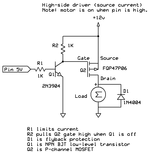
You can also control the fans high-side, with a P-channel fet and a small NPN transistor as level converter.
Then you can use the RPM pin of the fans to read fan speed.
Google e.g. "fan high-side PWM".
Leo..
-Why do you need these fans?
-Why and how do you want to control them?
-Does it require any input to run the fans at a certain speed?
Special effect in a driving simulator
I am going to write a program that will read telemetry from my simulator, and convert it into a value that makes sense for the fans. I would be natural to chose a min value between 1-255 where the fans start moving, and the max value be 255. This will then be sendt to the Arduino using serial over USB, and then the arduino will control the fans. I do not need any help with this part.
Yes the fans will need to gradually speed up. I am not in doubts about this part.
The only part I am asking for help regarding is the electronics, since this is the area where I am very green.
bfkmnemonic:
Ok. Odd since this MOSFET is in the official Arduino Starter Kit. But since it can only handle 10V it should be replaced. What cheap component can it be replaced with to so what I want?
You are correct that it is ODD that they would repeat the mistake time and time again.