Fatal bug in Sparkfun and Kris Winer's MPU9250 code

A bit ago someone raised questions about orientation angles produced by the Sparkfun MPU-9250 breakout board, using the provided AHRS code (Sparkfun made its own modifications to the code posted by Kris Winer on Github).

I decided to buy the Sparkfun MPU-9250 board to test it and discovered a major bug in both sets of software that produces nonsensical yaw, pitch and roll angles. It has been there for years, and others have noticed it (see issue #368 on Kris Winer's Github page), but has not been fixed. The code has never produced useful results.

Sparkfun's code (MPU2590BasicAHRS_I2C) doesn't work out of the box, either, because it assumes the wrong default I2C address for their own breakout board.

Sloppy work, all the way around.

The main issue is that the incorrect code inverts the handedness of the magnetometer coordinate system (which, due to the chip construction, has all axes swapped relative to the accelerometer/gyro axes).

A simple fix is to negate the magnetometer Z axis data, as SHOWN CORRECTED in the line below. Note the term "-myIMU.mz".

  MahonyQuaternionUpdate(myIMU.ax, myIMU.ay, myIMU.az, myIMU.gx * DEG_TO_RAD,
                         myIMU.gy * DEG_TO_RAD, myIMU.gz * DEG_TO_RAD, myIMU.my,
                         myIMU.mx, -myIMU.mz, myIMU.deltat);

Of course, to get useful data at all, the magnetometer MUST be correctly calibrated. So, do activate the built in calibration code, as in the modified Sparkfun example attached to this post. The calibration procedure is far from the best, and applies only the bias offsets, but works well enough to produce somewhat sensible results.

In the code attached, yaw = 0 corresponds to the accelerometer/gyro X axis pointing to magnetic North, with Z up, after proper magnetometer calibration.

UPDATE 3/24/2020: The stupid Sparkfun gyro/accelerometer calibration routine assumes that the sensor is kept still and horizontal, with Z up during initialization. The accelerometer should be recalibrated after this step or the pitch and roll angles will be wrong. Since the MPU-9250 has been discontinued, I recommend that people don't waste their time with it.

UPDATE 3/31/2020: I rewrote everything using a different MPU-9250 library and attached the new code at the end of reply #18, this thread. It all works well, provided that BOTH the accelerometer and the magnetometer are properly calibrated. See comments in .zip file.

MPU9250BasicAHRS_I2C.zip (4.86 KB)

Oi! Thanks for that bit of info.

Oh My Gosh!! It was me who posted the unfunctional code, and was seriously doubting i had any spark of intelligence left in me. You have absolutely no idea how much this has helped!!!
Amazing, thank you so much! That you bought a sensor just to figure it out....wow! Talk about helpfulness. Infinite numbers of thumbs up!

Hi, thank you very much for this. I have encountered 2 things on your code that I'd like to ask you:

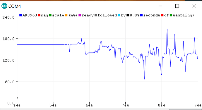
  1. The "MahonyQuaternionUpdate" produces results which oscillates too much (see picture attached)

Why do you think this happens?

  1. I've tried to use the " MadgwickQuaternionUpdate" using your fix, but I get values from 0-180 degrees only.

Is there a way to get values from 0-1=360 degrees?

thank you very much!


PS: This is the function I am using for the Madwick filter, which provides stable results but only on a 0-180 range:

MadgwickQuaternionUpdate(myIMU.ax, myIMU.ay, myIMU.az, myIMU.gx * DEG_TO_RAD,
myIMU.gy * DEG_TO_RAD, myIMU.gz * DEG_TO_RAD, myIMU.my,
myIMU.mx, -myIMU.mz, myIMU.deltat); //MADGWICK

  1. That is not oscillation, that is compass wrap (0-359 degrees).

  2. 0-359 is valid for only one angle in 3D angular systems, and that is usually yaw. For the other two, you are limited to 180 degrees each and then the orientations repeat. Or worse, you encounter "gimbal lock". See http://www.chrobotics.com/library/understanding-euler-angles

Hi, thanks for your prompt answer. Actually I've got those figures trying to move the sensor 90 degrees.

Look at this picture attached. This is the Madgwick filter when the sensor is just moving a little. This is a plot of the YAW. Values oscillate and for some reason, they are not very accurate.

Do you get good YAV values? meaning, you rotate the sensor 360 degrees (or 90) and you get a good plot?

Thanks!

This looks like what i get if i do not calibrate all systems completely. Dis you do the full calibration routine on Gyros, on Acellerometers and on Magnetometers?

Also, the SparkFun has the addition/subtraction of the calibration values commented out by default. You need to include them or you will not get usable results.....simply uncomment these in the code.

Thank you. I am using the code posted above by "jremington" and following the "move the sensor in eight shape" directives.

I am not sure if anything else is missing?

Thanks!

    myIMU.ax = (float)myIMU.accelCount[0] * myIMU.aRes; // - myIMU.accelBias[0];
    myIMU.ay = (float)myIMU.accelCount[1] * myIMU.aRes; // - myIMU.accelBias[1];
    myIMU.az = (float)myIMU.accelCount[2] * myIMU.aRes; // - myIMU.accelBias[2];

In his code the accel Biases are commented out. They need to be activated.

How do you move in 8's? The sensor needs to move in all directions about all axis.....just moving it in an 8 does not work if it not tilted, flipped and rotated while doing so....

Hi, thank you for replying and your help.

Your recommendation helped a little bit. But I am still unable to get a good 0-360 angle measurement for the YAW. I am starting to give up on this code.

See picture attached, that's what I got from several rotations over 360 in the Yaw direction. As you can see, it never goes down to zero or even to 360.

I honestly get better results just integrating the raw data and averaging it over certain time.

Were you ever able to get a good measurement of YAW angles with this code ?

I am getting very very usable results from the code. Even without the axis modification i was getting precice heading, however this was limited to one axis movement in the level plane.

See thread here

The only issues i am having is with the calibration routine....

Did you ever plot out the raw data of the 3 sensors? While rotating the sensor slowly about 1 axis? You will be able to see if your raw data is delivering rubbish....i have heard of drifty sensors from others on this forum.

In his code the accel Biases are commented out. They need to be activated.

If you do activate those corrections, you need to separately calibrate the accelerometer.

The built-in calibration routine estimates ONLY the magnetometer biases, which are usually much, much larger than the accelerometer biases.

The best procedure to calibrate both sensors is described in Tutorial: How to calibrate a compass (and accelerometer) with Arduino | Underwater Arduino Data Loggers

Ok great. Thanks

I am pasting your library that only prints the YAW values on line 337. If you have time, let me know if you get angles from 0-360 if you don't mind.

Thanks!

MPU9250BasicAHRS_I2C-fixed-working__.ino (15.9 KB)

  myIMU.calibrateMPU9250(myIMU.gyroBias, myIMU.accelBias);

yes this needs to be run also.

I get perfect angles -180 to +180, and added a code segment that adds (=subtracts) all values below 0 to 360.
(So a reading of -1 will give me 360 - 1 = 359)

I do get very accurate and jitter free readings on the mpu9250 with pitch values at or below 85deg.... above the gimbal lock begins showing significant effects and needs to be coped with differently....

After talking to Kris Winer and Sparkfun i'm still having my calibration issues on the 9250.

Symptoms have been described in other thread but it has died.....i find this one more fitting anyway.

Following issue: the calibration routine runs fine if run directly and unconditioned in setup. As soon as is conditioned, it returns nonsense....

calibrate=1;
If (calibrate=1) {}

You can check this by serial printing the values.....
Anyone had similar issues?

After talking to Kris Winer and Sparkfun

What did Kris Winer and Sparkfun have to say?

Surely you saw Winer's weird and unacceptable response to issue #368 on the Github page. I strongly suspect that neither Winer nor Sparkfun employees have bothered to understand the math involved in orientation calculations. They merely copy/paste code written by people who do understand it.

This is incorrect:

If (calibrate=1)

Sparkfun pointed me to their github, their github led me to kris, and kris understandably did not want to comment on a code that was altered and distributed by someone else.....sparkfun never responded again after that.

Acctually i did not....i will look tomorrow....

Yeah == is the syntax. Apologies

Hello :),
I am new to Arduino, and IMU sensors. I am using the MPU9250 for a very important project.
I am using the Sparkfun code with the modification that you gave for the Mahony quaternion update, and I uncommented the myIMU.magcal function as you said.
However, my values are still not correct. I have been trying for weeks now and searched for so many alternatives, and still don't understand how to calibrate this sensor. What is the calibration procedure? When asked to move the sensor in a figure 8, is there a specific way to do it? How to then calibrate accelerometer and gyro? I have attached the code I am using, as well as the ypr values at rest and a graph showing the curves for a roll and then a pitch movement. Roll seems to work with a small bias, however pitch and yaw are way off.
Please help me, it's going to make me crazy.

jremington:
A bit ago someone raised questions about orientation angles produced by the Sparkfun MPU-9250 breakout board, using the provided AHRS code (Sparkfun made its own modifications to the code posted by Kris Winer on Github).

I decided to buy the Sparkfun MPU-9250 board to test it and discovered a major bug in both sets of software that produces nonsensical yaw, pitch and roll angles. It has been there for years, and others have noticed it (see issue #368 on Kris Winer's Github page), but has not been fixed. The code has never produced useful results.

Sparkfun's code (MPU2590BasicAHRS_I2C) doesn't work out of the box, either, because it assumes the wrong default I2C address for their own breakout board.

Sloppy work, all the way around.

The main issue is that the incorrect code inverts the handedness of the magnetometer coordinate system (which, due to the chip construction, has all axes swapped relative to the accelerometer/gyro axes).

A simple fix is to negate the magnetometer Z axis data, as SHOWN CORRECTED in the line below. Note the term "-myIMU.mz".

  MahonyQuaternionUpdate(myIMU.ax, myIMU.ay, myIMU.az, myIMU.gx * DEG_TO_RAD,

myIMU.gy * DEG_TO_RAD, myIMU.gz * DEG_TO_RAD, myIMU.my,
                        myIMU.mx, -myIMU.mz, myIMU.deltat);


Of course, to get useful data at all, the magnetometer MUST be correctly calibrated. So, do activate the built in calibration code, as in the modified Sparkfun example attached to this post. The calibration procedure is far from the best, and applies only the bias offsets, but works well enough to produce somewhat sensible results. 

In the code attached, yaw = 0 corresponds to the accelerometer/gyro X axis pointing to magnetic North, with Z up, after proper magnetometer calibration.

**UPDATE 3/24/2020:** The stupid Sparkfun gyro/accelerometer calibration routine assumes that the sensor is kept still and horizontal, with Z up during initialization. **The accelerometer should be recalibrated after this step** or the pitch and roll angles will be wrong. Since the MPU-9250 has been discontinued, I recommend that people don't waste their time with it.

mpu9250.ino (21.2 KB)

Yaw Pirtch Roll values.pdf (264 KB)

There are additional problems with the Sparkfun code that make it essentially unusable. For example, the accelerometer bias adjustment is done incorrectly.

I ended up rewriting everything, using a different MPU-9250 library. I've attached it to this post.

There is a basic routine to collect magnetometer and accelerometer data for calibration, then a tilt-compensated compass application and a Mahony AHRS application that use the calibration results.

The latter applications work quite well IF AND ONLY IF you calibrate both the accelerometer and magnetometer carefully, following this tutorial.

Try it out and don't hesitate to post questions if you run into trouble.

New_MPU9250.zip (137 KB)

Hello,
Thank you for your quick reply and all the time invested in helping!
I used your calibration (MPU9250_cal) and Mahony codes. After using the raw data from the MPU9250_cal, I used the Magneto1.2 app to find my biases. I feel like the raw data and consequently the biases are really off for some reason. They are found in the attachment. I didn't use any formula to transform the raw data inputted into Magneto1.2, and used the norm of my location for the magnetic field, and a norm=1 for the acceleration since the MPU9250 gives values in mG. I replaced the biases in the Mahony code, like so:

float A_cal[6] = {-16388.614280, 356.032387, 16225.999603, 6.1e-5, -0.00, -0.00};
float M_cal[6] = {59.324302, -40.379123, 2.175487, 907.744845, 16.815642, 0.619070};
float G_off[3] = { 85.7, 532.3, -289.0}; //raw offsets, determined for gyro at rest
I also used my location's declination (5.08° E) to correct for the yaw, and replaced it in the code like so:
yaw = -yaw + 5.08;

At rest, the ypr angles are jumping nonsensically, as seen in the attachment.
Any idea on what I should do to fix this? Sorry if I'm inexperienced... When finding the raw data, (after keeping the sensor resting of course), I moved the sensor slowly, first one direction at a time (yaw, pitch and roll) and then randomly in all directions, as well as in a figure 8.
Is it possible that my chip has a problem? It might be important to note that for any code, the baud rate indicated in the code doesn't work on my chip and I have to choose a different baud rate (than the one indicated in the code) to get readable values.

Thank you so much!

jremington:
There are additional problems with the Sparkfun code that make it essentially unusable. For example, the accelerometer bias adjustment is done incorrectly.

I ended up rewriting everything, using a different MPU-9250 library. I've attached it to this post.

There is a basic routine to collect magnetometer and accelerometer data for calibration, then a tilt-compensated compass application and a Mahony AHRS application that use the calibration results.

The latter applications work quite well IF AND ONLY IF you calibrate both the accelerometer and magnetometer carefully, following this tutorial.

Try it out and don't hesitate to post questions if you run into trouble.

raw_data_calibration.zip (492 KB)