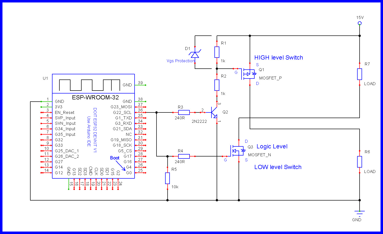
Yes, that's exactly what I was picturing in my head. Well, almost. I understand the voltage divider on the P-Channel. On the N-Channel, I was thinking it would need a pull-down resistor, but not thinking about a second resistor. I'm guessing this is for current limiting to protect the ESP?
Vgs is simply the voltage between the source (usually common "ground") and the gate. So if you had a circuit that would connect the gate to the +12V supply you must make sure that Vgs is safely above +12V. In my mind safely above +12V is ~ 20V.
Truck "12" volt voltage:
Can easily get to 16+ volts
Will have very high voltage spikes. They will be short and easy to filter out but the circuitry in your driver will need to be protected by various components (capacitors, TVS diodes etc).
The "automotive" power is a really nasty voltage source, it has all sorts of spikes, high frequency noise and ESD. Unfortunately this is the real world and part of any design is to protect your circuit from external damage.
In many automotive applications, the switching is done on the high side (high level).
Consider a limited example: If I want to control a small light, it will be supplied by power from a switch in the dash connected to 12V from the battery/power system. The light will be connected to chassis ground at the other end. There will likely not be a negative wire coming back to the switch.
To control it low-side, I would need to add a negative wire back to the switch. The light would always have 12V present.
It is possible to do high side switching with an N-channel using a bootstrap capacitor circuit. May end up being an easier to implement solution.
For my purposes, i will not be switching any factory devices, so running a ground back to the controller wouldn't be a problem.
I could potentially design it for both scenarios to be "future proof" though. Could two FETS be controlled by one output, maybe having a 3 pin connector with +12v, N-Channel output, P-Channel output? Could do 4, but i left out GND figuring in that scenario it would be likely grounded to the chassis.
I would be cautious with that. If the two FETs are controlling different devices, then theoretically it should not be a problem.
But in practice, you would run into limitations of the MCU pin in terms of current supply.
Good point on the current. If that were a possibility, it would have to be really low current draw between the two adding up to no more than the current allowed on the MCU pin. Which gives me another question, whether trying to control two transistors, or even just one, is there a recommended buffer on the current ratings? I mean, just for example, if the MCU has a spec of 500ma, should I try to use something that is a percentage less? Should I try to use something that only draws 60% or 80% or the allowed current? Or is the max rating ok because they always rate for less than what it could potentially handle?
Just had another thought on the "future proof" idea. If I use the i2c chip mentioned previously instead of controlling the MOSFET directly from the ESP, I could simply write the same data to two chips on different addresses (pretty sure you can't have two chips on the same address with i2c) one being set up for N-Channel connections and the other for P-Channel. It would certainly be a lot more circuitry, but could make both possible meaning you could hook up just about anything.
At switch-on, the two current limiting resistors, in parallel, will allow a draw of about 27 mA. I think that should be OK for the ESP32 but you may want to check the data sheet.
And once fully on, the FET will not be drawing a current. The current drawn by the NPN will depend.
You wouldn't even need to have them on different addresses, since they will both be sent the same command. But for simply running both FETs simultaneously as above, not really needed.
Though this may not even be an issue if you think the above circuit won't be a problem, just for future reference...
I don't know a lot about i2c, but as I understand it, because they have two-way communications, they should be on different addresses. That being said, when you send a command, does the slave respond to the master in any way if you are not attempting to read info from the chip? The reading it the other part of possible future plans. Being that there will be a master with multiple slave ESP-32s, I want to be able to poll the slaves and read the state of the pins from the i2c chips that each one is connected to. In some cases, the slave may be independently powered (like on a trailer with it's own battery) and it may be ideal to confirm if lighting has been turned on or off. Wouldn't two chips on the same address conflict if sending data back to the master?
In this case, you would want them to be on different addresses.
Some chips are configurable, like the PCF8574. There are 3 address lines, giving 8 possible addresses.