Filtering and storing data received over CAN Specifically OBD data

hello and thank you for taking the time to read this.
i am working on a project for something i have always wanted to do.
the overall goal of the project is to have a stand alone display which read information of the CAN bus in my car, and display it on an OLED or LCD.

so far i have started with some sketches that already exist for CAN and OBD. i have started with an OBD PID Request sketch.
what the sketch does: sends a "request" message to the car's ECM. then using the serial monitor the sketch displays all the CAN data received.

so far so good.

i want to send requests for multiple parameters to the ECM. Which i have accomplished.
i also want to display this information onto an OLED or LCD. I am comfortable using the displays.

here is the missing link:
after i send a PID request, i want to filter the CAN messages received, look for a specific message, and save only that message to somewhere in the RAM.

this program so far, will read all the CAN data on the bus. which is great but i am at a loss on how to filter out what i want in software.

Example:

send message 7DF 02 01 05 55 55 55 55 55 (this is the message to request coolant temp from the ECM)
i want to filter the incoming messages to be left with only the one message
what i am trying to filter for: 7E8 03 41 05 40 XX XX XX XX

i would like to be able to take byte 3 (the 40) and store it somewhere in ram

then, do the same thing for the next message that i send, and so on.

i have tried a couple of things, but have had no luck.

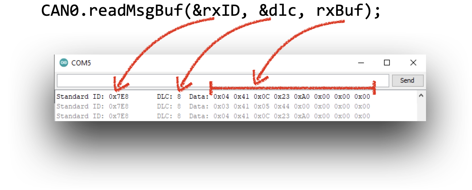
i have attached what some of the data looks like on the serial monitor in the picture

please let me know if there is any other information that i can provide to help in my quest for knowledge.

here is my code
i am not going to take credit for writing all of this. It came from one of the CAN libraries. I have made some small modifications to it.

#include <mcp_can.h>
#include <SPI.h>

#define standard 1  ///changed standard from 0 to 1
// 7E0/8 = Engine ECM
// 7E1/9 = Transmission ECM
#if standard == 1
  #define LISTEN_ID 0x7EA
  #define REPLY_ID 0x7E0
  #define FUNCTIONAL_ID 0x7DF
  #define FUNCTIONAL_ID_1 0x7DE //i added this one
  
#else
  #define LISTEN_ID 0x98DAF101
  #define REPLY_ID 0x98DA01F1
  #define FUNCTIONAL_ID 0x98DB33F1
#endif

// CAN TX Variables
unsigned long prevTx = 0;
unsigned int invlTx = 1000;
byte txData[] = {0x02,0x01,0x00,0x55,0x55,0x55,0x55,0x55};
byte txData1[] = {0x02,0x01,0x05,0x55,0x55,0x55,0x55,0x55};//i added this

// CAN RX Variables
unsigned long rxID;
byte dlc;
byte rxBuf[8];
char msgString[128];                        // Array to store serial string

// CAN Interrupt and Chip Select Pins
#define CAN0_INT 2                              /* Set INT to pin 2 (This rarely changes)   */
MCP_CAN CAN0(9);                                /* Set CS to pin 9 (Old shields use pin 10) */


void setup(){

  Serial.begin(115200);
  while(!Serial);
 
  // Initialize MCP2515 running at 16MHz with a baudrate of 500kb/s and the masks and filters disabled.
  if(CAN0.begin(MCP_STDEXT, CAN_500KBPS, MCP_16MHZ) == CAN_OK)
    Serial.println("MCP2515 Initialized Successfully!");
  else{
    Serial.println("Error Initializing MCP2515... Permanent failure!  Check your code & connections");
    while(1);
  }

//
//  // Allow all Standard IDs
//  CAN0.init_Mask(0,0x00000000);                // Init first mask...
//  CAN0.init_Filt(0,0x00000000);                // Init first filter...
//  CAN0.init_Filt(1,0x00000000);                // Init second filter...
//  // Allow all Extended IDs
//  CAN0.init_Mask(1,0x80000000);                // Init second mask...
//  CAN0.init_Filt(2,0x80000000);                // Init third filter...
//  CAN0.init_Filt(3,0x80000000);                // Init fouth filter...
//  CAN0.init_Filt(4,0x80000000);                // Init fifth filter...
//  CAN0.init_Filt(5,0x80000000);                // Init sixth filter...

#if standard == 1
  // Standard ID Filters
  CAN0.init_Mask(0,0x7F00000);                // Init first mask...
  CAN0.init_Filt(0,0x7DF0000);                // Init first filter...
  CAN0.init_Filt(1,0x7E10000);                // Init second filter...

  CAN0.init_Mask(1,0x7F00000);                // Init second mask...
  CAN0.init_Filt(2,0x7DF0000);                // Init third filter...
  CAN0.init_Filt(3,0x7E10000);                // Init fouth filter...
  CAN0.init_Filt(4,0x7DF0000);                // Init fifth filter...
  CAN0.init_Filt(5,0x7E10000);                // Init sixth filter...

#else
  // Extended ID Filters
  CAN0.init_Mask(0,0x90FF0000);                // Init first mask...
  CAN0.init_Filt(0,0x90DA0000);                // Init first filter...
  CAN0.init_Filt(1,0x90DB0000);                // Init second filter...

  CAN0.init_Mask(1,0x90FF0000);                // Init second mask...
  CAN0.init_Filt(2,0x90DA0000);                // Init third filter...
  CAN0.init_Filt(3,0x90DB0000);                // Init fouth filter...
  CAN0.init_Filt(4,0x90DA0000);                // Init fifth filter...
  CAN0.init_Filt(5,0x90DB0000);                // Init sixth filter...
#endif

  CAN0.setMode(MCP_NORMAL);                      // Set operation mode to normal so the MCP2515 sends acks to received data.

  // Having problems?  ======================================================
  // If you are not receiving any messages, uncomment the setMode line below
  // to test the wiring between the Ardunio and the protocol controller.
  // The message that this sketch sends should be instantly received.
  // ========================================================================
  //CAN0.setMode(MCP_LOOPBACK);

  pinMode(CAN0_INT, INPUT);                          // Configuring pin for /INT input
 
  Serial.println("Simple CAN OBD-II PID Request");
}

void loop(){

  if(!digitalRead(CAN0_INT)){                         // If CAN0_INT pin is low, read receive buffer
 
    CAN0.readMsgBuf(&rxID, &dlc, rxBuf);             // Get CAN data
  
    // Display received CAN data as we receive it.
    if((rxID & 0x80000000) == 0x80000000)     // Determine if ID is standard (11 bits) or extended (29 bits)
      sprintf(msgString, "Extended ID: 0x%.8lX  DLC: %1d  Data:", (rxID & 0x1FFFFFFF), dlc);
    else
      sprintf(msgString, "Standard ID: 0x%.3lX       DLC: %1d  Data:", rxID, dlc);
 
    Serial.print(msgString);
 
    if((rxID & 0x40000000) == 0x40000000){    // Determine if message is a remote request frame.
      sprintf(msgString, " REMOTE REQUEST FRAME");
      Serial.print(msgString);
    } else {
      for(byte i = 0; i<dlc; i++){
        sprintf(msgString, " 0x%.2X", rxBuf[i]);
        Serial.print(msgString);
      }
    }
      
    Serial.println();
  }
 
  /* Every 1000ms (One Second) send a request for PID 00           *
   * This PID responds back with 4 data bytes indicating the PIDs  *
   * between 0x01 and 0x20 that are supported by the vehicle.      */
  if((millis() - prevTx) >= invlTx){
    prevTx = millis();
    if(CAN0.sendMsgBuf(FUNCTIONAL_ID, 8, txData) == CAN_OK){
      Serial.println("Message Sent Successfully!");
    } else {
      Serial.println("Error Sending Message...");
    }    
  
    delay(500);
    
    if(CAN0.sendMsgBuf(FUNCTIONAL_ID, 8, txData1) == CAN_OK){
      Serial.println("Message Sent Successfully!");
    } else {
      Serial.println("Error Sending Message...");
    } 
  
  }
}

received CAN Data.png

received CAN Data.png

It might be slightly tricky to do it in a general purpose or elegant way, but for your first attempt I would think brute force would serve you well enough:

if(rxID == 0x7E8 && rxBuf[0] == 0x03 && rxBuf[1] == 0x41 && rxBuf[2] == 0x05)
  {
  CoolantTemp = rxBuf[3];  // You'll need to declare this variable somewhere
  }

The stuff you see on the serial monitor comes from the request

CAN0.readMsgBuf(&rxID, &dlc, rxBuf);

the 8 bytes of data you see in the Serial monitor come from this for() loop

     for (byte i = 0; i < dlc; i++) {
        sprintf(msgString, " 0x%.2X", rxBuf[i]);
        Serial.print(msgString);
      }

==> so it's the content of the rxBuf buffer and you have dlc bytes to print

it's just a matter of accessing

 rxBuf[the right byte number]

to extract stuff


So to @wildbill stuff is almost right, if you received
7E8 03 41 05 40 XX XX XX XX
the 0x03 is actually DLC so

if(rxID == 0x7E8 && dlc == 0x03 && rxBuf[0] == 0x41 && rxBuf[1] == 0x05) {
  CoolantTemp = rxBuf[2];  // You'll need to declare this variable somewhere
}

(assuming it's always 41 05 before the coolant temp)

I disagree. Dlc comes from here:

CAN0.readMsgBuf(&rxID, &dlc, rxBuf);

Obviously it was on the wire but it's not part of the 'data' packet. Note too, that it's eight, not three in this case.

yes dlc comes from there, as shown in my small drawing

I assumed that when OP said he is receiving

 7E8 03 41 05 40 XX XX XX XX

that was the plain answer from his request command "7DF 02 01 05 55 55 55 55 55"

the 7E8 was the standard ID (the rxID from the readMsgBuf call), then the next byte was the payload size (3), thus the DLC, saying that you really have 3 meaningful bytes + the rest is padded with 0x00 (the XX in OP's frame)

may be I'm wrong and you're right. I don't know enough about OBD

I suspect that the confusion is that the OP is likely reporting what was received based on what the borrowed code shows in the serial monitor. Since I know nothing about OBD either, we'll need a response from the OP to know for sure.

indeed.

at the end of the day, the data is somewhere in the rxBuf buffer, just need to get the right index :slight_smile:

Thank you all for your replies.
the code is borrowed from somewhere else.

what the serial monitor is doing, is not important to the end game of the project. However it is a nice to see during this phase of it.

i guess the fact that is is OBD II data is irrelevant over-all.

Wild Bill: i when i get a chance to set down on my bench i will try that.
having an elegant solution is not my first priority.

I think what you posted would give me a good start. Because i need 2 parts of the rx data. I need byte 2, (starting from the left, with the LSB being byte 0) to do a compare, to make sure it is the right parameter in the buffer to store to memory. this is the most important part. then i need byte 3 which is the raw hex data of the parameter.

so i will need to set up an "if rxbuffer [2] = 5, then save rxbuffer [3] to a predetermined memory location, which as pointed out, i will set up a variable for. it looks like the code you put in will do exactly that for me. i will try it and let you all know how it worked. it may be a day or two until i get to it.

J-M-L thank you for breaking that piece of it out. That is helpful. just to clarify, byte 0 (the 03) and byte 1 (the 41) are irrelevant for my purposes. the byte 3 is just stating that there are 3 bytes of data to follow. the 41 is a reply from the ECM stating that what you are seeing is mode 1 or real time data. i know it doesn't matter. but i apricate everyone sharing their knowledge so i figured i would share the little i know about CAN communications in general.
you are also correct in what you said. the RXId is the 7E8. that is the "header" of the message. the DLC is 8. that is letting the network know that there are 8 bytes of data that follows. What is in the bytes is not important to the DLC. but what i am after is in the RX Buffer. and byte zero like i said above, yes that means that there are 3 meaningful bytes to follow. the message has 4 useful bytes total.

so overall, what the serial monitor is reporting that is what i want to look at, compare and save.

to parse down what i have said here, at the end of the day
after the arduino transmits 7DF 02 01 05 55 55 55 55 55
i want to read the message buffer until the message i am looking for is in there
the 7E8 03 41 05 40 XX XX XX XX
that is where the compare comes into play, to make sure i have the right data in the buffer.
because the CAN0.readMsgBuf(&rxID, &dlc, rxBuf) will just keep reading data over and over again.

i hope my explanation clears up some of the questions that were asked by everyone.
if anyone has any more ideas to try i am all ears (or eyes in this case).
in the mean time i will get to my bench at the next earliest chance i have and report back my results.

I guess a follow up, does anyone know of a memory dump command through the serial monitor
so i can actively check that the memory location of the byte i store to make sure the program is
working correctly

again thank you all

well i guess for the memory dump, i could just write a line in to serial print the memory location. so that seems like a straight forward way to do that

Yes that’s how you print stuff out, the same way the rxBuf was printed out by the for loop I highlighted.

I’m still confused if you’ll receive the DLC as part of the frame as you mention
7E8 03 41 05 40 XX XX XX XX

So I would have thought 7E8 is the ID, 03 the DLC and then you have 7 bytes with only 3 meaningful

Or is DLC just always 8 and thus not part of the frame ?

i see the confusion now.
i left out the DLC part, because for this project, it is always 8.
but the 03 in the first data byte means there is only 3 useful bytes of data after the first byte.
i will get the hang of this eventually. thank you for working with me.

One can get the Freematcis library and look at how they do the thing.

What I did was just get a Freematcis ODBCII which I connected a ESP32 and the display for my own custom display.

Remember that if you, through trial and error send the wrong codes on the CAN Bus it will be an unknown as to what will receive the data and what the device will do with the data and what, ultimately, happens to your car.

If you are not going to use a premade ODBCII dongle, then get a ODBCII ECM simulator. With a simulator if the wrong PID codes are sent your car's steering won't lock up whiles your driving it.

Check out the OBD parser part of my SafeString tutorial
It decodes the OBD return based on the number of valid chars.
And then decodes the hex numbers to real numbers

However the format your posts mention appear to be a bit different.
Are there multiple OBD formats?

Idahowalker:
One can get the Freematcis library and look at how they do the thing.

What I did was just get a Freematcis ODBCII which I connected a ESP32 and the display for my own custom display.

Remember that if you, through trial and error send the wrong codes on the CAN Bus it will be an unknown as to what will receive the data and what the device will do with the data and what, ultimately, happens to your car.

If you are not going to use a premade ODBCII dongle, then get a ODBCII ECM simulator. With a simulator if the wrong PID codes are sent your car's steering won't lock up whiles your driving it.

Idaho walker, is the freematics OBD connector still for sale? i ran across their website, and it did not look like it was kept very much up to date. also the few reviews i could find for the website did not look promising. However if you or someone on this forum has purchased from them recently, then i may give it a shot. I also downloaded to sketch they had on there for their modules and had no luck in compiling them.
i am using the seeeed studios CAN module. it has been sitting on my shelf for a while but i really wanted to give it a try.

DRMPF
thank you for posting that i had a quick glace of your code.
it looks like its set up for ELM 327. i do not know all the specifics but i know the ELM is set up a specific way with and designed for interfacing with OBD. i am using a seed studio CAN shield just to communicate with the CAN on the vehicle. so the format for sending and receiving messages is different than it is with the ELM 327. is there an elm 327 to Arduino dongle/shield that is readily available. i do not have the appetite to design any hardware at the moment.

@SmallBrownBike
Yes the code is for ELMduino that works with the ELM327 OBD-II scanner. I am not an expert (or even a user of) ODB. Just helped out a user to replace Arduino Strings and c-strings with SafeString to solve his constant reboot problems.
Looks like there are two OBD protocols from OBD1 vs OBD2: Difference Between OBD1 and OBD2 - OBD Station

OBD2 provide better and more standardized vehicle protocols and system checks data. OBD1 needs corded connection while OBD2 can be connected hands freely via Bluetooth or wifi.

wildbill
i had intended on working on this over the weekend. but i am sure you know how it is when you get excited about something and want to try it. I used the piece of code you gave me, and i had some promising results.

i have some tweeking to do. i need to do some more work with the CAN data once it gets into the buffer, as the data i am storing to memory is not always consistent. sometimes it misses a data byte.
but thanks to your tip i am on the right track.

i am experimenting with how the data is fed into the buffer from the CAN lines, and i think that will help. basically i can get it to work flawlessly on the bench, but in the car, sometimes the memory dump of the integer is zero. i am sure it will come down to a timing problem somewhere.

The interesting thing about the car i am using this on, is that there must be a gateway that goes to the OBD connector, because the datalink is empty of any data unless it gets a request from a scan tool. i just thought i would share this. because 90% of the cars i have worked on have a library of data on the CAN lines at any given time. regardless of if there is a scan tool or not. So i think i am going to find the gateway and see if there is another set of can lines to look at. However for the time being, i will keep using the regular OBD connector.

here is the code that i have modified using the lines of code you provided.
please excuse the sloppiness as it is still under development.

/* CAN OBD & UDS Simple PID Request


#include <mcp_can.h>
#include <SPI.h>

int coolant_temp;
int vehicle_speed;
int vehicle_speed_1A;
int vehicle_speed_1B;
int coolant_temp_1;

//int ecm_volt_1A;
//int ecm_volt_1B;

#define standard 1  ///changed standard from 0 to 1
// 7E0/8 = Engine ECM
// 7E1/9 = Transmission ECM
#if standard == 1
  #define LISTEN_ID 0x7EA
  #define REPLY_ID 0x7E0
  #define FUNCTIONAL_ID 0x7DF
  #define FUNCTIONAL_ID_1 0x7DE //i added this one
  
#else
  #define LISTEN_ID 0x98DAF101
  #define REPLY_ID 0x98DA01F1
  #define FUNCTIONAL_ID 0x98DB33F1
#endif

// CAN TX Variables
unsigned long prevTx = 0;
unsigned int invlTx = 1000;
byte txData[] = {0x02,0x01,0x00,0x55,0x55,0x55,0x55,0x55};
byte txData1[] = {0x02,0x01,0x05,0x55,0x55,0x55,0x55,0x55};//i added this
byte txData2[] = {0x02,0x01,0x42,0x55,0x55,0x55,0x55,0x55};//i added this
//byte txData2[] = {0x02,0x01,0x0D,0x55,0x55,0x55,0x55,0x55};//i added this

// CAN RX Variables
unsigned long rxID;
byte dlc;
byte rxBuf[8];
char msgString[128];                        // Array to store serial string

// CAN Interrupt and Chip Select Pins
#define CAN0_INT 2                              /* Set INT to pin 2 (This rarely changes)   */
MCP_CAN CAN0(9);                                /* Set CS to pin 9 (Old shields use pin 10) */


void setup(){

  Serial.begin(115200);
  while(!Serial);
 
  // Initialize MCP2515 running at 16MHz with a baudrate of 500kb/s and the masks and filters disabled.
  if(CAN0.begin(MCP_STDEXT, CAN_500KBPS, MCP_16MHZ) == CAN_OK)
    Serial.println("MCP2515 Initialized Successfully!");
  else{
    Serial.println("Error Initializing MCP2515... Permanent failure!  Check your code & connections");
    while(1);
  }


#if standard == 1
  // Standard ID Filters
  CAN0.init_Mask(0,0x7F00000);                // Init first mask...
  CAN0.init_Filt(0,0x7DF0000);                // Init first filter...
  CAN0.init_Filt(1,0x7E10000);                // Init second filter...

  CAN0.init_Mask(1,0x7F00000);                // Init second mask...
  CAN0.init_Filt(2,0x7DF0000);                // Init third filter...
  CAN0.init_Filt(3,0x7E10000);                // Init fouth filter...
  CAN0.init_Filt(4,0x7DF0000);                // Init fifth filter...
  CAN0.init_Filt(5,0x7E10000);                // Init sixth filter...

#else
  // Extended ID Filters
  CAN0.init_Mask(0,0x90FF0000);                // Init first mask...
  CAN0.init_Filt(0,0x90DA0000);                // Init first filter...
  CAN0.init_Filt(1,0x90DB0000);                // Init second filter...

  CAN0.init_Mask(1,0x90FF0000);                // Init second mask...
  CAN0.init_Filt(2,0x90DA0000);                // Init third filter...
  CAN0.init_Filt(3,0x90DB0000);                // Init fouth filter...
  CAN0.init_Filt(4,0x90DA0000);                // Init fifth filter...
  CAN0.init_Filt(5,0x90DB0000);                // Init sixth filter...
#endif

  CAN0.setMode(MCP_NORMAL);                      // Set operation mode to normal so the MCP2515 sends acks to received data.

  pinMode(CAN0_INT, INPUT);                          // Configuring pin for /INT input
 
  Serial.println("Simple CAN OBD-II PID Request");
}

void loop(){

  if(!digitalRead(CAN0_INT)){                         // If CAN0_INT pin is low, read receive buffer
 
    CAN0.readMsgBuf(&rxID, &dlc, rxBuf);             // Get CAN data
  
    // Display received CAN data as we receive it.
    if((rxID & 0x80000000) == 0x80000000)     // Determine if ID is standard (11 bits) or extended (29 bits)
      sprintf(msgString, "Extended ID: 0x%.8lX  DLC: %1d  Data:", (rxID & 0x1FFFFFFF), dlc);
    else
      sprintf(msgString, "Standard ID: 0x%.3lX       DLC: %1d  Data:", rxID, dlc);
 
    Serial.print(msgString);
    
    Serial.println();
    Serial.print("111111111111"); 
    
    if((rxID & 0x40000000) == 0x40000000){    // Determine if message is a remote request frame.
      sprintf(msgString, " REMOTE REQUEST FRAME");
      Serial.print(msgString);
    } else {
      for(byte i = 0; i<dlc; i++){
        sprintf(msgString, " 0x%.2X", rxBuf[i]);
        Serial.print(msgString);
      }
    }
//  if(rxBuf[1] == 0x41 && rxBuf[2] == 0x05) 
//  coolant_temp_1 = rxBuf[3];  // parameter to save
  
  if(rxBuf[1] == 0x41 && rxBuf[2] == 0x42) 
  vehicle_speed_1A = rxBuf[3];
  if(rxBuf[1] == 0x41 && rxBuf[2] == 0x42)
  vehicle_speed_1B = rxBuf[4];  // parameter to save
    
  if(rxBuf[1] == 0x41 && rxBuf[2] == 0x05) 
  coolant_temp_1 = rxBuf[3];  // parameter to save
  
    Serial.println();
     Serial.print("22222222222"); 
  }
 
  /* Every 1000ms (One Second) send a request for PID 00           *
   * This PID responds back with 4 data bytes indicating the PIDs  *
   * between 0x01 and 0x20 that are supported by the vehicle.      */
  if((millis() - prevTx) >= invlTx){
    prevTx = millis();

//send first CAN message.  this is the request for supported PIDS    
    if(CAN0.sendMsgBuf(FUNCTIONAL_ID, 8, txData) == CAN_OK){
      Serial.println("Message Sent Successfully!");
    } else {
      Serial.println("Error Sending Message...");
    }    
  
    delay(100);

//send Second CAN message.  this is the request for Coolant Temp    
    if(CAN0.sendMsgBuf(FUNCTIONAL_ID, 8, txData1) == CAN_OK){
      Serial.println("Message Sent Successfully!");
    } else {
      Serial.println("Error Sending Message...");
    } 
//  if(!digitalRead(CAN0_INT)){                         // If CAN0_INT pin is low, read receive buffer
 
//    CAN0.readMsgBuf(&rxID, &dlc, rxBuf);             // Get CAN data
//  }

  if(rxID == 0x7E8 && dlc == 0x08 && rxBuf[1] == 0x41 && rxBuf[2] == 0x05) {
  coolant_temp = rxBuf[3];  // parameter to save
}
//  Serial.println("-Coolant Temp"); 
//  Serial.println(coolant_temp);
  Serial.println("-Coolant Temp_1"); 
  Serial.println(coolant_temp_1);
    delay(100);

//send third CAN message.  this is the request for ECM VOltage    
    if(CAN0.sendMsgBuf(FUNCTIONAL_ID, 8, txData2) == CAN_OK){
      Serial.println("Message Sent Successfully!");
    } else {
      Serial.println("Error Sending Message...");
    } 
//  if(!digitalRead(CAN0_INT)){                         // If CAN0_INT pin is low, read receive buffer
 
//    CAN0.readMsgBuf(&rxID, &dlc, rxBuf);             // Get CAN data
//  }

  if(rxID == 0x7E8 && dlc == 0x08 && rxBuf[1] == 0x41 && rxBuf[2] == 0x0D) {
  vehicle_speed = rxBuf[3];  // parameter to save
}
//  Serial.println("-vehicle speed"); 
//  Serial.println(vehicle_speed);
  Serial.println("-vehicle speed_1"); 
  Serial.println(vehicle_speed_1A);
  Serial.println(vehicle_speed_1B);
    delay(100);


  }
}

Oi! I could not find them either. Sparkfun makes an ODBCII dongle as do a few others.

This topic was automatically closed 120 days after the last reply. New replies are no longer allowed.