Just purchased my first Arduino after a long time sitting on the fence, am enjoying it so far but have run into an issue that has me scratching my head (well not actually an issue just not sure what's going on).
The first project is to connect an LED in line with a switch and 220 ohm resistor and have the LED activate using the switch.
I am an ex car mechanic so my day to day used to include a lot of auto electrical work. I'm not completely new to the concept of how a circuit works (although I'm by no means an electrical engineer).
After some research I found that Arduino push buttons are diagonally connected with their opposite ends, the project instructions were to have the switch so that two pins were on one side of the board, and the other two pins were on the other side of the not-connected bread board.
I used my multimetre and confirmed that the two pins directly opposite each other were always connected, but the two diagonally opposite were only connected once the button was pushed. The book and diagram had it configured as such:
I'm at a loss for why this works correctly? If the pin directly opposite is connected, shouldn't the circuit bypass the need to use the button when connected like this?
It seems that the Arduino has no part to play in what you are doing except to provide 5V. Is that intentional ?
As to the switch, the way to connect it to ensure that the 2 pins that you use are across the switch and not connected together is, as you say, to use diagonally opposite pins
It is possible to use 2 switch pins on the same side of the switch but there is a 50/50 chance that they will be connected together rather than switched
If the 2 switch pins that you are using are, in fact, connected together in the switch, then the LED should be on at all times regardless of whether you press the switch. Which pairs of "same side" pins did you measure ? Test the ones that you are using
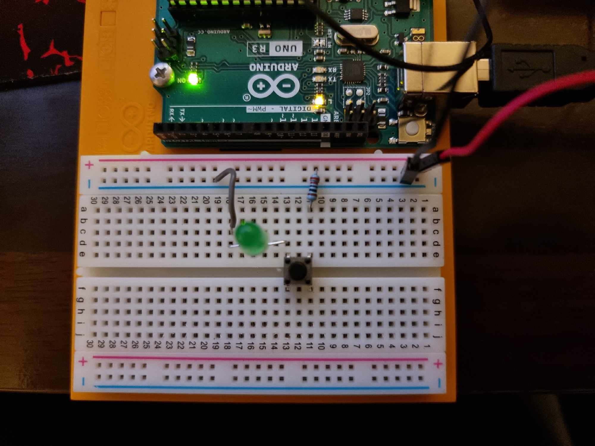
I hope the photo below is not confusing. The two red circles which are the only pins touching the circuit have continuity when tested off the board.
The green circles are the pins that are continuous only when the button is pushed. In this configuration, the circuit should be connected 100% of the time and the LED should always be on, however it is working correctly.
My confusion is why this is working correctly (when the button is pushed only) when the two opposite pins in red are connected all the time.
What exactly on that page answered your question ?
If the 2 button pins that you are using are permanently connected to each other, which you say they are, then pressing the button should have no effect
This led me to believe he mis-interpreted his meter measurements. That page elaborates on the switches internal mechanism and orientation.
These switches can be confusing to newbies.