First electronics project - to illuminate a light when motorcycle is in 6th gear

I know very little about electronics, but am doing my best to learn.

My motorcycle doesn’t have a gear indicator and when accelerating through the gears it’s easy to lose track, think you’ve got another gear to go and attempt to change up, only to find that you haven’t – most irritating! I used to have an aftermarket digital gear indicator fitted but it became unreliable and I removed it, and in fact I only need to know when I’ve changed into top, not where I am in the lower gears.

A German electronics engineer who owned the same model bike as me used to make and sell a digital gear indicator for it but has now ceased production and I’ve been unable to contact him. However, what is still available on his website are descriptions of his unit’s hardware (based around an Atmega128A-AU) and the software he developed, the latter including the ratios in each gear of the pulse frequencies for the RPM sensor (12V, coming from the ECU) and the Speed sensor (5V, reading the rotation of the 6th gear pinion on the gearbox output shaft). In 6th gear these are 33.3 pulses/1000 rpm and 40.3 pulses/metre respectively, giving a ratio of 0.826.

In order to fit my now-defunct gear indicator I had to splice into a switched +12V cable, an earth/ground cable, the cable powering the 12V bulb that shows when you're in neutral, and the cables conveying the information on engine speed and road speed mentioned above to the rev counter and speedometer respectively. All of these cables are easily accessible.

For my first electronics project I’d like to try to make a (6th) gear indicator, and from what I’ve read buying an Arduino (and learning how to write code for it!) would be a good starting point – but which one?

The unit would need to be:

• Easily programmed by a novice such as myself
  
• Compact, so that it can be hidden away out of sight

• Rugged, so that it’ll survive the vibrations and jolts experienced on a bike

Furthermore, I’d need to be able to:

• Mount the unit in a waterproof enclosure 

• Find a way of illuminating a remotely-mounted LED (via a relay?) when RPM/Speed = 0.826

• Work out a way of powering the device from the bike’s ‘polluted’ 12V supply

Am I asking too much of an Arduino?

Thanks in advance for any suggestions as to how I should proceed.

Can you link to this ?
If he did it, then I'm sure you can, maybe with a bit of help here. You've already identified most of the important points/constraints.

Hi 6v6gt, thanks for your reply.

I should be able to post some links but the webpages are written in German and are in http rather than https - are either of those a problem?

People here are quite adept at using ChatGPT/Google translate etc. Also insecure web pages should not scare away too many otherwise useful contributors. Just post what you've got but make it clear when links land on a page in the German language.

Not at all. But you might benefit from working away from the final deployment environment to get the software almost perfect first.

Use a more convenient Arduino than the tiniest might be, forget about providing power in the automotive environment, forget about mechanical issues that will also arise there and so forth.

Depending on the signals, it is may be possible to do it in simulation

Here's a recent simulation I wrote for another inquirer that kinda works like a speedometer, demonstrating measuring and "displaying" a pulse rate:

a7

Welcome!

That is an advanced program for a beginner but it can be done. I suggest you take a break and get a copy of the Arduino Cookbook and skim it cover to cover, that will teach you a lot about Arduino and how to use it.

Thanks a7 and gilshultz for your inputs, much appreciated. Here's some further info, as requested by 6v6gt:

The German electronics engineer I mentioned, Christian Vieth, used to own, as I still do, a Yamaha FZS1000 (Fazer 1000), sold between 2001-2005 and known outside Europe as the FZ1. The next incarnation (2006-2015), a completely different bike, was, confusingly, known as the FZ1 in all markets. I mention this to make it clear that where Christian speaks of the FZS1000 he’s referring to ‘our’ 1st generation bike, whereas where he mentions the FZ1 (as he does at one point in ‘Preparing sensor signals’ within ‘Building your own gear indicator, Part 1, Hardware’, which I’ll send a link to below) he means the 2nd generation bike, which isn’t relevant to my project. Christian incorporated his gear indicator into a device that he called the Multigauge, which replaced the original fuel gauge in the dashboard and served several functions, such as fuel gauge, gear indicator, water temperature gauge, ambient temperature gauge, etc.

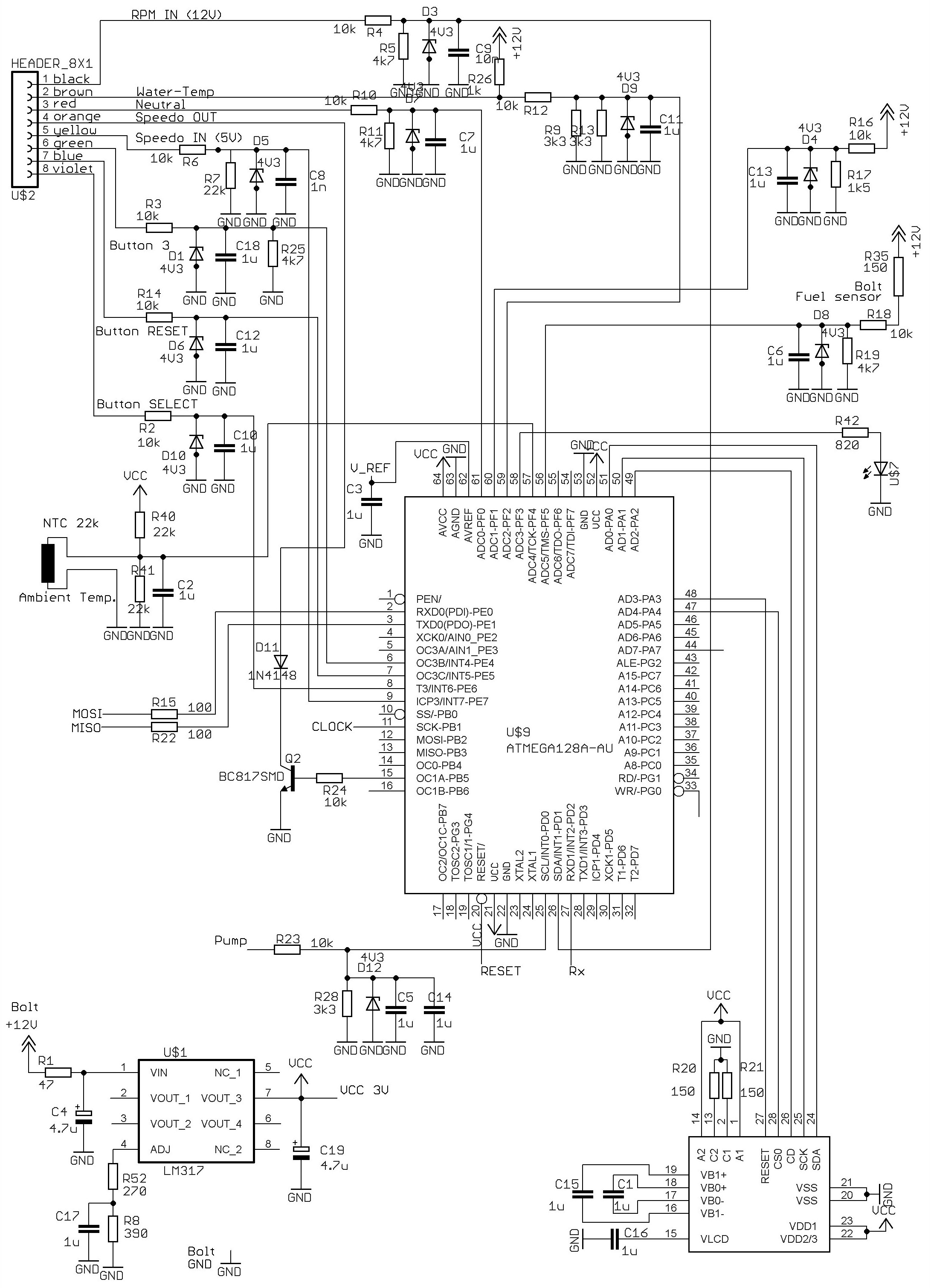
The Multigauge came with cables attached, which were to be soldered by the installer onto the PCB inside the instrument cluster. According to his website Christian started working on the Multigauge in about 2004, refining it through several versions over subsequent years. The circuit diagram linked to below is for V9, which I think may have been the last one produced. Top left are 8 inputs into the Multigauge from the cables soldered to the PCB inside the bike’s instrument binnacle; the Multigauge’s power supply and display are (I think!) shown bottom left and bottom right respectively. The inputs most of interest to me are, naturally, #1 (black) ‘RPM IN (12V)’ and #5 (yellow) ‘Speedo IN (5V)’.

http://cvieth.bplaced.net/bilder/ganganzeige/diy/V9_1_Schematic.JPG

Below are links to webpages (written in German) describing Christian’s hardware and his software; I’ve found that Chrome’s translations into English make a lot of sense. Although in the article on hardware Christian states that the Speed sensor generates 40 pulses/metre, in a later post on a Fazer technical forum he amended this figure to 40.3 pulses/metre, which I think is closer to the mark. Either way, in the article on software I don’t find exactly the same figure as him for the ratio RPM/Speed in 6th gear: he states 0.822, whereas I find at least 0.826 however many decimal places I use in the calculation of the figure for pulses per 1000rpm (2000/60). BTW, in the same forum post, Christian said of the Speed sensor that it was “open collector output, 1k resistor inside the cockpit” and of the RPM signal that “Duty cycle doesn’t matter, frequency is important”.

http://cvieth.bplaced.net/ganganzeige_diy_hw.html

http://cvieth.bplaced.net/ganganzeige_diy_sw.html

Thanks again for your encouragement. It's after 11pm here in the UK, so I'll sign off now.

From the schematics etc he is using the rising edge of the sped pulse. You can use either the key is the edge. I would assume he is using the interrupt for counting etc. That would give him the RPM/milage/km. Looking at the header he is looking for an active high which is supplied by the switch 12V. The temperature appears to be an analog signal.

He took care with the 12V that powers the unit including reverse polarity. There is good filtering in that design. This probably the most important piece of the design, it protects all of the electronics from the 12V power. He also took care on the inputs to protect the processor.

I did some searching through my notes and memory and came up with this, hopefully it helps and explains what a lot of the parts are in the design form Note:A motorcycle 12 V electrical system is much harsher than a car’s because the wiring is smaller, the battery is smaller, and the regulator/rectifier is usually simpler. I may have some errors as my background is mainly US Automotive.

You should assume very dirty power unless you fully isolate your electronics.

Below is an engineering view of realistic transients seen on motorcycle 12 V buses.

Load Dump (Worst Case): +40 V to +80 V
When the battery disconnects while the alternator is charging (loose terminals, corroded connectors), the regulator cannot absorb the spike fast enough.
Typical motorcycle load dump: +40 to +60 V for 100 ms to 400 ms
Extreme cases: up to +80 V for short durations
This will destroy unprotected electronics.

  1. Starter Motor Dropout: 4–7 V

When the starter engages:
Bus voltage can collapse to 6–8 V normally
In cold weather or with a weak battery: as low as 4 V
Your device must survive undervoltage and not reset or corrupt memory.

  1. Ignition Coil Inductive Spikes: +100 V to -200 V (common)
    Motorcycle ignition coils produce large inductive kicks that couple into the wiring harness:
    Positive spikes easily +60 to +120 V
    Negative spikes -100 to -200 V on poorly grounded systems
    Very fast rise times: nanoseconds to microseconds
    These can enter through the DC wiring or through electro-magnetic coupling.

  2. Rectifier Ripple: 1–3 V peak-to-peak
    Compared to cars, motorcycle regulator/rectifiers often produce more AC ripple on the 12 V bus:
    1–3 V ripple is common
    Bad rectifier: 5–8 V p-p (dangerous for electronics)
    Switching regulators on bikes are often "shunt" designs, meaning excess alternator current is simply dumped as heat, adding noise.

  3. Voltage Overshoot after Start: 15–16 V
    Immediately after the starter motor releases:
    The regulator may overshoot
    Brief spike to 15–16.5 V is normal
    With aging components: 17–18 V possible

  4. Reverse Polarity Momentary Events

Jump-start mistakes or bad grounds can create:
-12 V to -14 V for tens of milliseconds
Momentary negative spikes on shared grounds
Devices must survive accidental reverse connections.

  1. Switching Transients from Fans, Relays, Pumps
    Small inductive loads (cooling fans, fuel pumps, relays) create:
    ±40–60 V spikes

Duration: microseconds to milliseconds

  1. EMI / RF Noise
    Motorcycle frames have poor shielding. Expect:
    Wideband EMI from ignition
    Alternator whine in the audio range (100–3000 Hz)
    High-frequency spikes from cheap USB chargers

QUICK SUMMARY: WHAT YOU MUST DESIGN FOR
At minimum:
Transient suppression: TVS diode (SMBJ or SMCJ series) at 600 W or more
Reverse polarity protection: MOSFET or Schottky
DC filtering: LC filter or buck converter with good input filtering
Load dump survival: 50+ V rated input components
Undervoltage tolerance: Must run down to 6 V, survive to 4 V
EMI protection: Grounding, ferrite beads, shielded wires

If you measured speed by monitoring wheel rotations and monitored RPM by sensing a spark plug cable, a few conditional statements if(y > s1 && y < s2 && x > r1 && x < r2) would give you the answer.

You will need to collect live data of RPM in each gear from idle to maxRPM to graph RPM v speed in each gear for the conditional tree.

You mean if(speed/rpm > ratio1 && speed/rpm < ratio2) don't you?

I meant to use "ranges" (over ratios) because ranges are easy to recognize over ratios. Ratios and ranges will yield the same result. Any search for "motorcycle speed versus rpm" will show a "range" graph... but not a "ratio" graph (yes, you can refine the search for "ratio" graphs).

Thanks all.

Christian stresses just these points in the description of his hardware. AFAIK he's sold quite a few of these units, and I've not seen any complaints about unreliability on any of the Fazer forums I've visited.

I didn't think I'd need to do this as Christian has already given this info for exactly the same model of bike as mine. In 6th gear RPM/Speed has been measured as approximately 0.826, so I assumed I'd just need to construct a conditional statement something like "If ratio > 0.8 then YES, otherwise NO"? Surely as long as the software can distinguish between the ratio for 6th gear (the only one I'm interested in) and 5th (0.764) then all's good? :slightly_smiling_face:

The links (post #7) lead to some impressive builds showing some considerable soldering feats including using a solder board with a pitch way in excess of the pin pitch of the main chip:


But that was for a complete instrumentation console with gear indicator, fuel level, temperature, etc. etc.
If you are interested only in an indicator for a specific gear, your require only 2 main inputs (related to engine speed and road speed) and one output (a led). This would be a considerable simplification.

A MCU with at least 2 external interrupts should do the trick, something that is available in a DIP package would be preferred i guess. Or maybe just the one external interrupt (RPM)and let pinChangeInterrupts deal with the other one. (speed) In that case an ATtiny13 could work.
Programming wise it really isn't much.

Basically similar to a car but about 2 or 3 times worse.
Opto-isolation for the sensing is an obvious step, which leaves the power supply rail.

Which would be easily handled and I bet adequately by the crude frequency to servo angle demo I linked.

I'll see if it's straightforward to have two pulse generators in the wokwi project.

From there on it's just tuning and frills. If it was me, I'd go full on with a gear indicator set of LEDs.

a7

That's what I was hoping to hear! Perhaps rather than using a relay to illuminate a 12V LED as I'd imagined, I could instead use a low-powered LED connected directly to the board - it's not as if it's a warning signal that needs to be bright enough to catch my attention.

I'm intrigued by your post Deva_Rishi - having Googled a bit I think I understand how the ATtiny13, with only one dedicated external interrupt pin, can be configured to receive a second by using its Pin Change Interrupt feature. I've also seen a description of how the ATtiny13 can be programmed using the Arduino IDE:

https://www.instructables.com/Updated-Guide-on-How-to-Program-an-Attiny13-or-13a/

If that could all work then, given the small size of the ATtiny13, perhaps I could construct my own compact board that also incorporates protection against 'dirty' power and corruption of the sensor signals?

Yes that is more or less how i do it, though i use a different core

https://mcudude.github.io/MicroCore/package_MCUdude_MicroCore_index.json

And i use them so often for things that i built a dedicated uploader to connect to the UNO.

Keep in mind that the ATtiny13 has reached it's end of life, but the 13a is still easily available. They are so cheap 9in China) that getting a few won't hurt much.

You could consider powering the 12v led with a transistor or possibly even better an Opto-coupler.
On a bike i would probably want the MCU in a metal box for EMI shielding, it being that close to the engine's ignition. Although a plastic enclosure would probably do the trick.

Well they fire a different ISR, which i think is what is required. You could count both pulses using PCINT, but if those pulses are fired near simultaneously, there is a chance of losing pulse on one or the other theoretically.
All the ISR's do really is counting.

The Attiny13a is small when it comes to flash size (1KB only) but the program won't have to do much. As long as your math can stick with using integers and not use floats, then it should fit just fine. It is a matter of doing multiplications before division. If you can't manage the calculus using integers (though i know i can) then a different MCU would be better. Floating point math will easily take up half of the flash space. It will always be a fairly snug fit, but i doubt you'll need more than about 50% of the flash, and also the 64 byte RAM should hardly be used.

Yes i think so. A few 1N4007 diodes, a bunch of capacitors and a 5v linear regulator should be enough to filter the spikes and prevent inverted voltages and create a stable 5v power source (mind you the ATtiny can run on way less than that just fine) A couple of opto-couplers for the sensors and an LED and a few resistors. I guess with the speed you will use a hall-sensor and you intend to tap into the induction of the ignition for the RPM

I agree with you. The model motor data is good for the application.

I'd start with this advice:

That is get some sort of development board ( Uno R3 / Nano etc ). You'll need a breadboard, wires, a few leds etc. etc. Maybe a kit would be a good idea. There are many to choose from.

The actual device that you use for the final project will probably be an 8 pin ATtiny of some sort but you can also think about that later.

Your main problem is going to be understanding the raw signals that you are getting from the cables you have spliced into and how to clean them up and interpret them.

Fortunately, it looks like most of this work has been done from the schematic in your link in post #7

I guess the engine speed will be easier because the bike can be static while you are running the engine at various speeds. So this could be the first thing to try.

So, to start it off, I suggest you initiate an Arduino project, on your chosen development board, to measure the RPM of your bike, using the circuit components highlighted in blue on the diagram below, and print the results to the serial monitor at regular intervals.

Errata: Speedo OUT has ben highlighted but Speedo IN was intended.

Here is the difference between if(y > s1 && y < s2 && x > r1 && x < r2) and if(speed/rpm > ratio1 && speed/rpm < ratio2)
The range (or ranges) test:

The ratio test:


As you can see, testing ranges is very limited, you would need many tests to cover only one gear ratio and many more for all gears...