First Project: Arduino Fahrenheit Temp Display

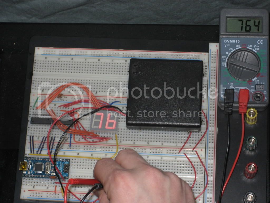
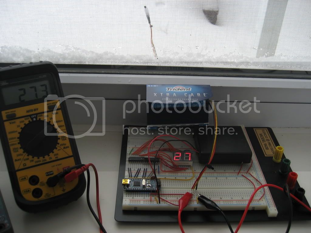
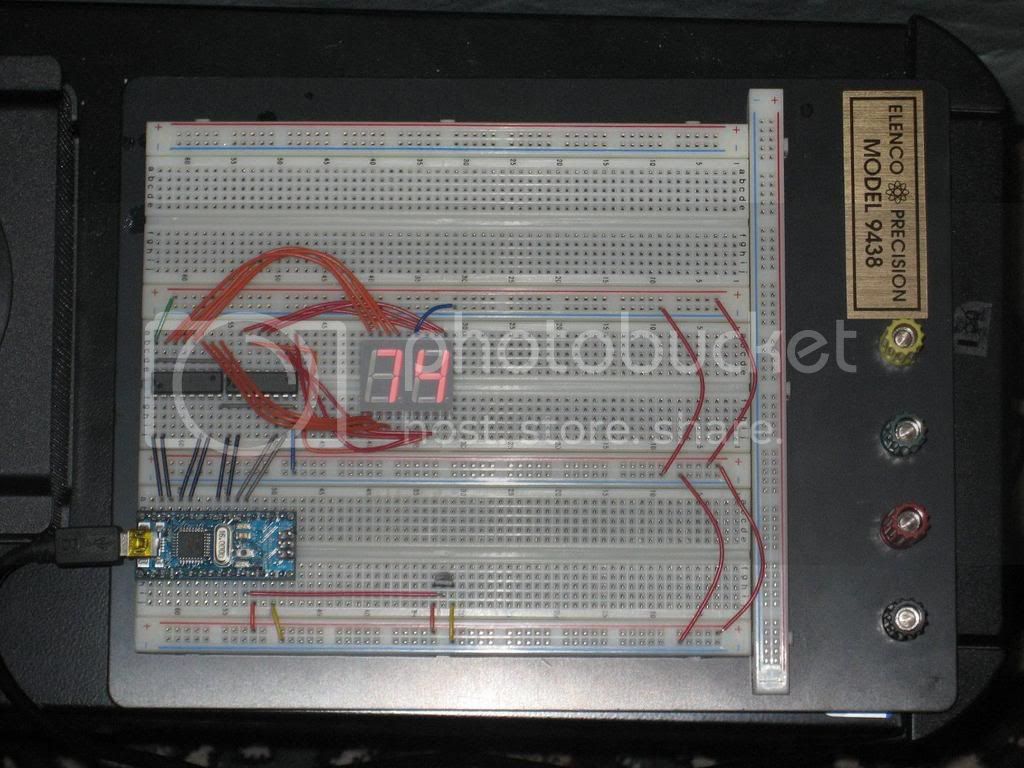
For my first Arduino based project I decided to take the output of am LM34 Fahrenheit temperature sensor (could be adapted for the LM35 easily) and have it read out on a 2 digit 7 segment display. You can see my horrid code and a flash-annihiliated picture below. The jumper wires were precut standard lengths, so it isn't pretty, but it works. The ICs are 74LS48 7-segment display drivers. They convert a BCD number into the 7 signals required to make the equivalent decimal number. Hope someone finds this useful.

int MSBpins[] = {2,5,4,3};        // digital pins to use for the MSB 7-segment display
int LSBpins[] = {8,11,10,9};        // digital pins to use for the LSB 7-segment display
int sensor_pin = 0;        // the analog pin for LM34 temp sensor
float sensor_reading = 0.0;        // variable to store the value coming from the sensor
float vref = 1.084;        // variable to store the voltage reference used (check for validity with a DMM)
int fahrenheit = 0;        // variable to store the actual temperature
int acquisition_timer = 1000;        // variable to control the time between updates (in ms)
int MSBdecimal = 0;        // variable to store the decimal MSB of the fahrenheit temperature
int LSBdecimal = 0;        // variable to store the decimal LSB of the fahrenheit temperature

void setup()
{
  pinMode( sensor_pin, INPUT );        // set LM34 temp sensor pin as an input
  analogReference(INTERNAL);        // set the analog reference to the 1.1V internal reference
  for ( int i = 0; i < 4; i++ )        // set all pins mentioned in the arrays to outputs
  {
    pinMode( MSBpins[i], OUTPUT );
    pinMode( LSBpins[i], OUTPUT );
  }
  delay(1000);
}

void loop()
{
  
  sensor_reading = analogRead(sensor_pin);         // stores the digitized (0 - 1023) analog reading from the LM34
  fahrenheit = (100.0 * sensor_reading * vref)/1023;   // calculates the actual fahrenheit temperature
  MSBdecimal = fahrenheit / 10;     // separates the MSB of the fahrenheit temperature and stores it
  LSBdecimal = fahrenheit % 10;     // separates the LSB of the fahrenheit temperature and stores it
  switch(MSBdecimal)
  {
    case 0:
      digitalWrite( MSBpins[0] , LOW );
      digitalWrite( MSBpins[1] , LOW );
      digitalWrite( MSBpins[2] , LOW );
      digitalWrite( MSBpins[3] , LOW );
      break;
    case 1:
      digitalWrite( MSBpins[0] , LOW );
      digitalWrite( MSBpins[1] , LOW );
      digitalWrite( MSBpins[2] , LOW );
      digitalWrite( MSBpins[3] , HIGH );
      break;
    case 2:
      digitalWrite( MSBpins[0] , LOW );
      digitalWrite( MSBpins[1] , LOW );
      digitalWrite( MSBpins[2] , HIGH );
      digitalWrite( MSBpins[3] , LOW );
      break;
    case 3:
      digitalWrite( MSBpins[0] , LOW );
      digitalWrite( MSBpins[1] , LOW );
      digitalWrite( MSBpins[2] , HIGH );
      digitalWrite( MSBpins[3] , HIGH );
      break;
    case 4:
      digitalWrite( MSBpins[0] , LOW );
      digitalWrite( MSBpins[1] , HIGH );
      digitalWrite( MSBpins[2] , LOW );
      digitalWrite( MSBpins[3] , LOW );
      break;
    case 5:
      digitalWrite( MSBpins[0] , LOW );
      digitalWrite( MSBpins[1] , HIGH );
      digitalWrite( MSBpins[2] , LOW );
      digitalWrite( MSBpins[3] , HIGH );
      break;
    case 6:
      digitalWrite( MSBpins[0] , LOW );
      digitalWrite( MSBpins[1] , HIGH );
      digitalWrite( MSBpins[2] , HIGH );
      digitalWrite( MSBpins[3] , LOW );
      break;
    case 7:
      digitalWrite( MSBpins[0] , LOW );
      digitalWrite( MSBpins[1] , HIGH );
      digitalWrite( MSBpins[2] , HIGH );
      digitalWrite( MSBpins[3] , HIGH );
      break;
    case 8:
      digitalWrite( MSBpins[0] , HIGH );
      digitalWrite( MSBpins[1] , LOW );
      digitalWrite( MSBpins[2] , LOW );
      digitalWrite( MSBpins[3] , LOW );
      break;
    case 9:
      digitalWrite( MSBpins[0] , HIGH );
      digitalWrite( MSBpins[1] , LOW );
      digitalWrite( MSBpins[2] , LOW );
      digitalWrite( MSBpins[3] , HIGH );
      break;
    default:
      digitalWrite( MSBpins[0] , HIGH );
      digitalWrite( MSBpins[1] , HIGH );
      digitalWrite( MSBpins[2] , HIGH );
      digitalWrite( MSBpins[3] , HIGH );
      break;
  }
  switch(LSBdecimal)
  {
    case 0:
      digitalWrite( LSBpins[0] , LOW );
      digitalWrite( LSBpins[1] , LOW );
      digitalWrite( LSBpins[2] , LOW );
      digitalWrite( LSBpins[3] , LOW );
      break;
    case 1:
      digitalWrite( LSBpins[0] , LOW );
      digitalWrite( LSBpins[1] , LOW );
      digitalWrite( LSBpins[2] , LOW );
      digitalWrite( LSBpins[3] , HIGH );
      break;
    case 2:
      digitalWrite( LSBpins[0] , LOW );
      digitalWrite( LSBpins[1] , LOW );
      digitalWrite( LSBpins[2] , HIGH );
      digitalWrite( LSBpins[3] , LOW );
      break;
    case 3:
      digitalWrite( LSBpins[0] , LOW );
      digitalWrite( LSBpins[1] , LOW );
      digitalWrite( LSBpins[2] , HIGH );
      digitalWrite( LSBpins[3] , HIGH );
      break;
    case 4:
      digitalWrite( LSBpins[0] , LOW );
      digitalWrite( LSBpins[1] , HIGH );
      digitalWrite( LSBpins[2] , LOW );
      digitalWrite( LSBpins[3] , LOW );
      break;
    case 5:
      digitalWrite( LSBpins[0] , LOW );
      digitalWrite( LSBpins[1] , HIGH );
      digitalWrite( LSBpins[2] , LOW );
      digitalWrite( LSBpins[3] , HIGH );
      break;
    case 6:
      digitalWrite( LSBpins[0] , LOW );
      digitalWrite( LSBpins[1] , HIGH );
      digitalWrite( LSBpins[2] , HIGH );
      digitalWrite( LSBpins[3] , LOW );
      break;
    case 7:
      digitalWrite( LSBpins[0] , LOW );
      digitalWrite( LSBpins[1] , HIGH );
      digitalWrite( LSBpins[2] , HIGH );
      digitalWrite( LSBpins[3] , HIGH );
      break;
    case 8:
      digitalWrite( LSBpins[0] , HIGH );
      digitalWrite( LSBpins[1] , LOW );
      digitalWrite( LSBpins[2] , LOW );
      digitalWrite( LSBpins[3] , LOW );
      break;
    case 9:
      digitalWrite( LSBpins[0] , HIGH );
      digitalWrite( LSBpins[1] , LOW );
      digitalWrite( LSBpins[2] , LOW );
      digitalWrite( LSBpins[3] , HIGH );
      break;
  }

hey man, good job... i just went over to radioshack the other day and got myself an lcd display like ures, except with only one symbol display... can u teach me how to hook it up... i cant find any tutorials anywhere for this!

If you just have the one digit to display, you could use eight pins on the Arduino, one for each element on the display, then light specific elements by setting those pins to high.

However, you will probably need more than one digit to do anything useful, and running two digits this way will use up all your pins

A better learning experience would be to check the shiftout tutorial in the playground, that will show you how to wire up the serial to parallel shift converter, then each link on the 7 digit display gets one of the outputs from the shift converter IC.

Then you should be able to use the shiftout command to light which bars you choose, and run as many digits as you wish, off the same three pins.

I can't specifically get a datasheet for that model, but I think I have the same one purchased elsewhere. If you cannot find the datasheet, you can just probe it with 5V and ground until you find the common pin, and then map out the rest of the pins.

http://www.ee.washington.edu/stores/DataSheets/optoelec/7segled.pdf

it might either be 74 or 72 (common anode or cathode)

k thx guys, il see wat i can do from here

I added an output that blinks one of the decimal point LEDs on the display every time the loop runs to show the user how often it is updating.

int LSBpins[] = {3,4,5,2};        // digital pins to use for the MSB 7-segment display
int MSBpins[] = {9,10,11,8};        // digital pins to use for the LSB 7-segment display
int sensor_pin = 0;        // the analog pin for LM34 temp sensor
int rate_pin = 12;        // the digital pin to blink the decimal point of the display with each acquisition
float sensor_reading = 0.0;        // variable to store the value coming from the sensor
float vref = 1.084;        // variable to store the voltage reference used (check for validity with a DMM)
int fahrenheit = 0;        // variable to store the actual temperature
int acquisition_timer = 1000;        // variable to control the time between updates (in ms)
int MSBdecimal = 0;        // variable to store the decimal MSB of the fahrenheit temperature
int LSBdecimal = 0;        // variable to store the decimal LSB of the fahrenheit temperature

void setup()
{
  pinMode( rate_pin, OUTPUT );
  pinMode( sensor_pin, INPUT );        // set LM34 temp sensor pin as an input
  analogReference(INTERNAL);        // set the analog reference to the 1.1V internal reference
  for ( int i = 0; i < 4; i++ )        // set all pins mentioned in the arrays to outputs
  {
    pinMode( MSBpins[i], OUTPUT );
    pinMode( LSBpins[i], OUTPUT );
  }
  
  delay(1000);
}

void loop()
{
  sensor_reading = analogRead(sensor_pin);         // stores the digitized (0 - 1023) analog reading from the LM34
  fahrenheit = (100.0 * sensor_reading * vref)/1023;   // calculates the actual fahrenheit temperature
  MSBdecimal = fahrenheit / 10;     // separates the MSB of the fahrenheit temperature and stores it
  LSBdecimal = fahrenheit % 10;     // separates the LSB of the fahrenheit temperature and stores it
  digitalWrite( rate_pin, LOW );
  switch(MSBdecimal)
  {
    case 0:
      digitalWrite( MSBpins[0] , LOW );
      digitalWrite( MSBpins[1] , LOW );
      digitalWrite( MSBpins[2] , LOW );
      digitalWrite( MSBpins[3] , LOW );
      break;
    case 1:
      digitalWrite( MSBpins[0] , LOW );
      digitalWrite( MSBpins[1] , LOW );
      digitalWrite( MSBpins[2] , LOW );
      digitalWrite( MSBpins[3] , HIGH );
      break;
    case 2:
      digitalWrite( MSBpins[0] , LOW );
      digitalWrite( MSBpins[1] , LOW );
      digitalWrite( MSBpins[2] , HIGH );
      digitalWrite( MSBpins[3] , LOW );
      break;
    case 3:
      digitalWrite( MSBpins[0] , LOW );
      digitalWrite( MSBpins[1] , LOW );
      digitalWrite( MSBpins[2] , HIGH );
      digitalWrite( MSBpins[3] , HIGH );
      break;
    case 4:
      digitalWrite( MSBpins[0] , LOW );
      digitalWrite( MSBpins[1] , HIGH );
      digitalWrite( MSBpins[2] , LOW );
      digitalWrite( MSBpins[3] , LOW );
      break;
    case 5:
      digitalWrite( MSBpins[0] , LOW );
      digitalWrite( MSBpins[1] , HIGH );
      digitalWrite( MSBpins[2] , LOW );
      digitalWrite( MSBpins[3] , HIGH );
      break;
    case 6:
      digitalWrite( MSBpins[0] , LOW );
      digitalWrite( MSBpins[1] , HIGH );
      digitalWrite( MSBpins[2] , HIGH );
      digitalWrite( MSBpins[3] , LOW );
      break;
    case 7:
      digitalWrite( MSBpins[0] , LOW );
      digitalWrite( MSBpins[1] , HIGH );
      digitalWrite( MSBpins[2] , HIGH );
      digitalWrite( MSBpins[3] , HIGH );
      break;
    case 8:
      digitalWrite( MSBpins[0] , HIGH );
      digitalWrite( MSBpins[1] , LOW );
      digitalWrite( MSBpins[2] , LOW );
      digitalWrite( MSBpins[3] , LOW );
      break;
    case 9:
      digitalWrite( MSBpins[0] , HIGH );
      digitalWrite( MSBpins[1] , LOW );
      digitalWrite( MSBpins[2] , LOW );
      digitalWrite( MSBpins[3] , HIGH );
      break;
    default:
      digitalWrite( MSBpins[0] , HIGH );
      digitalWrite( MSBpins[1] , HIGH );
      digitalWrite( MSBpins[2] , HIGH );
      digitalWrite( MSBpins[3] , HIGH );
      break;
  }
  switch(LSBdecimal)
  {
    case 0:
      digitalWrite( LSBpins[0] , LOW );
      digitalWrite( LSBpins[1] , LOW );
      digitalWrite( LSBpins[2] , LOW );
      digitalWrite( LSBpins[3] , LOW );
      break;
    case 1:
      digitalWrite( LSBpins[0] , LOW );
      digitalWrite( LSBpins[1] , LOW );
      digitalWrite( LSBpins[2] , LOW );
      digitalWrite( LSBpins[3] , HIGH );
      break;
    case 2:
      digitalWrite( LSBpins[0] , LOW );
      digitalWrite( LSBpins[1] , LOW );
      digitalWrite( LSBpins[2] , HIGH );
      digitalWrite( LSBpins[3] , LOW );
      break;
    case 3:
      digitalWrite( LSBpins[0] , LOW );
      digitalWrite( LSBpins[1] , LOW );
      digitalWrite( LSBpins[2] , HIGH );
      digitalWrite( LSBpins[3] , HIGH );
      break;
    case 4:
      digitalWrite( LSBpins[0] , LOW );
      digitalWrite( LSBpins[1] , HIGH );
      digitalWrite( LSBpins[2] , LOW );
      digitalWrite( LSBpins[3] , LOW );
      break;
    case 5:
      digitalWrite( LSBpins[0] , LOW );
      digitalWrite( LSBpins[1] , HIGH );
      digitalWrite( LSBpins[2] , LOW );
      digitalWrite( LSBpins[3] , HIGH );
      break;
    case 6:
      digitalWrite( LSBpins[0] , LOW );
      digitalWrite( LSBpins[1] , HIGH );
      digitalWrite( LSBpins[2] , HIGH );
      digitalWrite( LSBpins[3] , LOW );
      break;
    case 7:
      digitalWrite( LSBpins[0] , LOW );
      digitalWrite( LSBpins[1] , HIGH );
      digitalWrite( LSBpins[2] , HIGH );
      digitalWrite( LSBpins[3] , HIGH );
      break;
    case 8:
      digitalWrite( LSBpins[0] , HIGH );
      digitalWrite( LSBpins[1] , LOW );
      digitalWrite( LSBpins[2] , LOW );
      digitalWrite( LSBpins[3] , LOW );
      break;
    case 9:
      digitalWrite( LSBpins[0] , HIGH );
      digitalWrite( LSBpins[1] , LOW );
      digitalWrite( LSBpins[2] , LOW );
      digitalWrite( LSBpins[3] , HIGH );
      break;
  }
  delay(acquisition_timer);
  digitalWrite( rate_pin, HIGH ); 
}

I added a 4x AA power supply (over 6V) and changed the power pin of the sensor to the 6V source. It's not supposed to operate at less than 5V. I also have my cheaper DMM next to it to show the accuracy of the formula I used.

Aha, you have a Velleman DVM-810! Nice little multimeter, but hard to find nowadays. I have a similar, but yellow, multimeter that's handy to take to things like Dorkbot evenings. When I need a more esoteric meter, I use the HP 3456A, which has 6.5 digits and will show a resistor's value changing as it warms up in the palm of your hand.

yeah the velleman is nice and portable, but it's not especially accurate. It's still nice since i paid $5.90 for it.

I got an Ideal DMM for my primary multimeter, I hope to own a fluke sometime soon.

Because I'm bored and like talking to myself, I made this picture showing the temperature sensor outside. The gum is to shield the LED display from glare.

The gum is to shield the LED display from glare.

Aww, I thought you might have found a way to sell product placement adds in hobby pictures, and I wanted in on the action!

How accurate is your temperature reading compared to a commercial thermometer / local weather readings? I always wanted my own little weather station at the house, I just can't bring myself to spend hundreds of dollars on them. Building one for hundreds of dollars, that's another story.

:slight_smile:

Well I'd have to check, but the weather said 25 when it was 26, this thing has guaranteed accuracy to 1F, so do the math. There is some error in the reading because its converting a float to an integer. If I set the reference to 2V exactly or something with a voltage divider, I could increase the accuracy.

The easiest way to check or correct temperature calibration is to use a ice bath (32F or 0C) and boiling water (212F or 100C) for two reference points.

Lefty

I implemented a couple lines of code to serially grab the data from the arduino and display it on the serial monitor, hope to graph it later.

BTW it says 19F right now, Weather.com says 18F for my area. So far

It's proven to be fairly accurate, though I still would like a more accurate external analog reference. The 1.1V internal reference limits my temperature reading to 110F (If I had a third digit, which would be easy).

ooooooooooooooooh it actually says 18F right now, sweet.