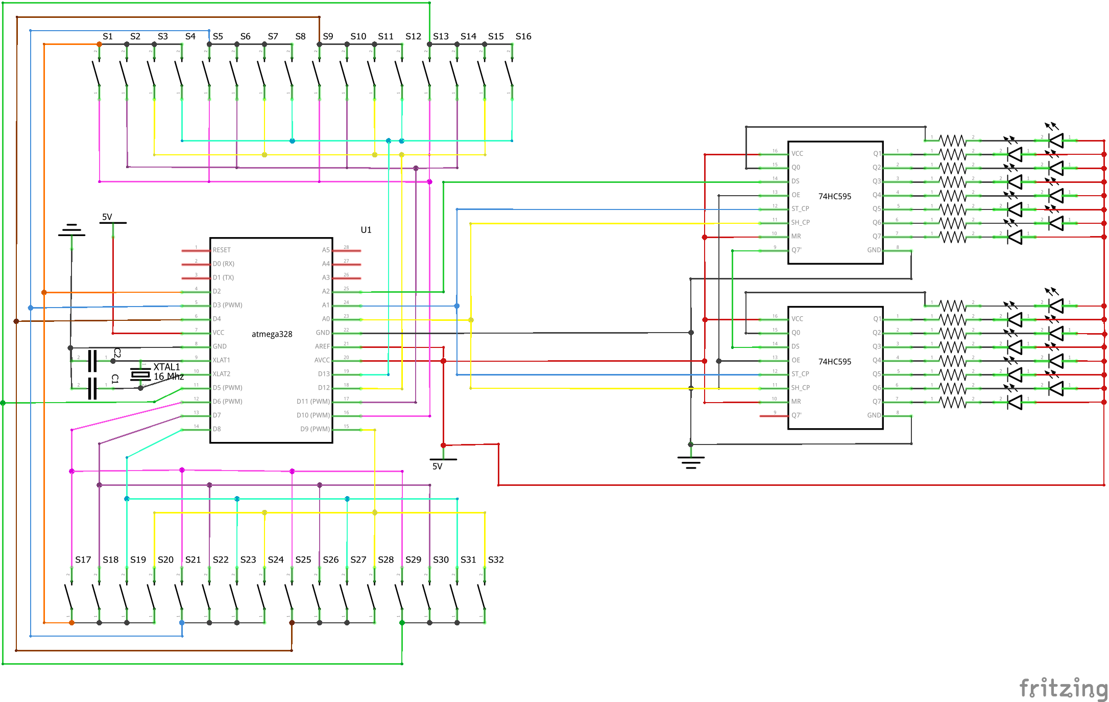
I have 16 lights that to control from 32 separate discreet buttons. The on buttons will all be connected with one cat5 line about 10 ft away from the board and the off buttons will be connected with a second cat5 line built into the board. Unfortunately Fritzing doesn't allow for "striped" wires so I had to use alternate colors. The 16 lights are going to be run off two 595's. In the schematic they are LED's that sink current through the 595's but in the final project that's going to be a 16 relay sainsmart board (hence the sinking current). Should I use resistors when connecting the sainsmart to the 595's?
Since this is my first time making a schematic I wanted to throw it up and see if there are any glaring issues that will cause problems when I build it. It seems that all of the keypad examples are for 3x4 or 4x4 keypads, hopefully the keypad library will work with a 4x8 keypad.
here is the link to the code for this, I'm sure it could be shortened but not sure how. - Arduino Cloud