Your module already has diodes. So adding diodes in parallel does not make much difference.
On the H-bridge, the "body" diodes on the non conducting MOSFETs are the "free wheeling" diodes.
But they do not allow free wheeling. They ar protecting diodes. They deliver current to whatever the voltage of your power source is.
The direct diode as suggested by OP is a real freewheel diode... and I think that is the reason why it runs with more torque. But (as stated by OP) it cannot be used in reverse. I guess there is no easy fix for that (these drivers ara always buit like this).
You may however use half the H bridge... that will at least prevent that you can try to reverse your motor (and destroy either the diode or your bridge...
It also allows you to have either freewheel or 'active breaking'... I will try to find the link for you...
Found:
I wouldn't welcome breaking. Braking would be okay.
Sounds the same, means something else...
So indeed, I meant braking!
OK, so I managed to find and translate a datasheet, and it turns out the driver has a fast and slow decay mode. The default was fast decay, which apparently is known for lower torque and worse speed control. I just tried it in slow decay mode, and it's working like magic. Speed control is basically perfectly linear, and it has good torque even at low RPM and low PWM.
Stall current is quite a bit higher across the PWM range too, which is to be expected since the torque is higher.
So now I'm confused why exactly adding a flyback diode behaved better? Was it behaving more equivalent to a slow decay mode by providing the EMF path, just as how slow decay mode shorts the motor together during the PWM off cycles?
Now that I've found the solution though, I'm still confused why slow-decay has higher torque. I'd have thought that shorting the terminals to brake the motor during PWM off time would slow it down more and lead to less torque, but this isn't the case.
Maybe the inductance of the motor is such that when fast decaying the current during PWM off, the current doesn't have enough time to ramp up again during the PWM on cycle? Whereas the slow decay keep the current flowing during the off cycle so that the on cycle doesn't have to fight the inductance's "inertia" on every on cycle?
This still seems counter-intuitive though, as the slow decay would allow the back-emf to provide backwards voltage, thereby causing current to flow the other way?
Either way, I seem to have found my solution. I guess I'll have to do more reading on slow vs fast decay
I'm glad you found a solution. As for what is going on, my response is from experience driving DC motors. With your driver IC things must be different. I don't know what the "fast decay" vs the "slow decay" means to the motor (electrically).
Fast/slow decay aren't terms specific to the IC I'm using.
With your driver IC things must be different
I'm not sure what about my IC seems different? It's behaving exactly like any driver in fast/slow decay mode.
Those are general motor driver terms. https://www.allaboutcircuits.com/technical-articles/difference-slow-decay-mode-fast-decay-mode-h-bridge-dc-motor-applications/
I don't understand why slow decay has higher PWM torque, and am still confused about that, but the driver is definitely acting just like any driver with these modes.
Note this adafruit article also says that slow decay has better controllability and low speed torque, but doesn't explain the physics around it, which is really what still confuses me. Choosing Decay Mode and PWM Frequency | Improve Brushed DC Motor Performance | Adafruit Learning System
I just realised my response wasn't actually super helpful in explaining.
TL;DR:
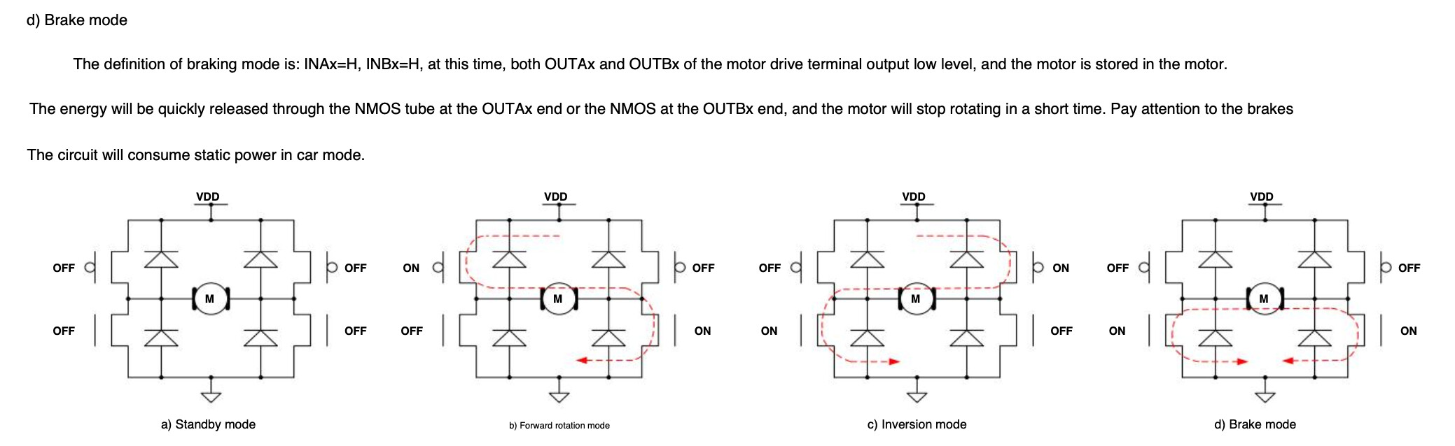
Fast decay in this instance = the driver leaves the mosfets floating during PWM off time, and the excess current flows through the body diodes of the H bridge, theoretically back to the power source. When going from 100% to 0%, this allows the motor to coast.
Slow decay = the driver shorts the motor pins together during PWM off. This mode also stops the motor almost instantly when going from 100% to 0%, as the shorted motor brakes itself. Hence why it's confusing to me that this mode also increases forward torque during low duty cycle PWM, as intuitively I'd have thought that the motor would be braking itself during PWM off and "fighting" itself, as opposed to increasing torque.
EDIT: Note though, that (minimum startup duty cycle excluded), fast decay runs the motor faster than slow decay in low load, with the same PWM input.
I.E.
50% slow decay is approx 50% of full speed under low load, with I'd estimate 75% or so of full torque.
50% fast decay is approx 75% of full speed under low load, with I'd estimate about 30% of full torque.
So in a sense the motor is being slowed by the PWM off cycles in slow decay mode, yet also has higher forward torque. This is completely paradoxical to me and I'd love to understand why.
Hi,
This should help too.
From the site referenced in post #1.
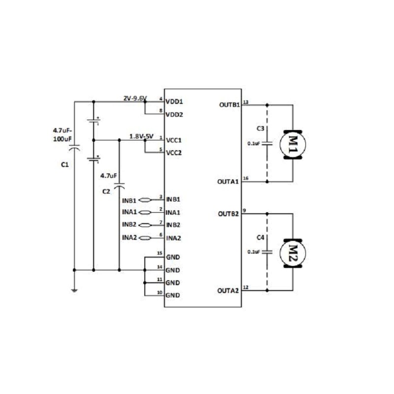
Can you please redraw your schematics using the correct pinouts.
You show themotor connected across pins 5 and 6!!!!! the data sheet shows 9 and 12 or 13 and 16.
PLEASE an image of a hand drawn circuit will be fine.
Please include component names and pin labels.
Tom... ![]()
![]()
![]()
![]()
Yeah I was using the chip in the diagram as a black box example, not intended to represent my actual layout. IRL I'm using the exact layout as shown in that reference diagram. The question isn't about how to use the driver, but more specifically about why the motor torque increases when running the driver in slow-decay mode, or when running a single flyback diode across the motor.
Hi,
Can you please post your code in a new post?
Thanks.. Tom... ![]()
![]()
![]()
![]()
Literally just the default AnalogInOutSerial sketch, with pin numbers and PWM frequency changed (running at 25khz currently). Ultimately the sketch is purely just generating a PWM frequency, nothing fancy.
The driver is put into slow decay mode by holding the other direction control high all the time, so during PWM off time both forward and backward are high (the driver specifically supports this), and during PWM on time, only one direction is high and the other is low.
This makes the PWM control inverse, where 0 is full speed and 255 is no speed, but that's not a problem.
Here's the relevant screenshots from the translated datasheet in case it provides clarity:
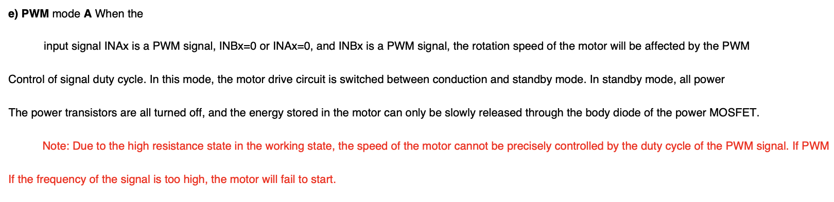
PWM Mode A is fast decay.
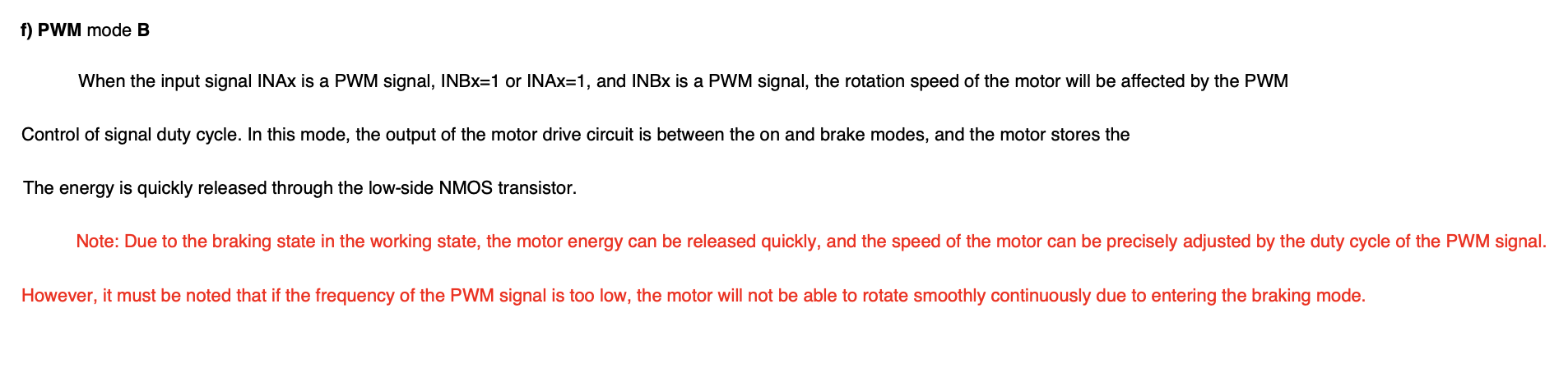
PWM Mode B is slow decay.
Hi,
What if you drop the PWM frequency lower by a factor of 10, 2.5KHz?
Tom.... ![]()
![]()
![]()
![]()
I played around with different frequencies quite a bit. Fast decay worked more reliably and has higher torque at very low frequencies (30-100hz), but is audible which is a problem. Anything above about 1khz behaved the same, noise aside. Bad low end torque and speed control.
Slow decay seems to behave similarly at any frequency, although is much noisier than fast decay at low frequencies (no doubt because the braking at the same frequency adds noise). Again though, anything above about 1khz functionally behaves very similar, with the only difference being the audible noise.
If I push to very high frequency in either mode (60khz and above), torque starts to drop off, presumably because of the driver switching time. The datasheet recommends between 10khz-50khz. 25khz seemed like the best compromise, reducing switching time and inefficiency, while being outside of the audible range.
Here's the full translated datasheet for posterity:
MX1515-SinotechMixicElectronics-3-2.pdf (1014.8 KB)
(It says MX1515 instead of MX1919, but seems functionally identical. I think the difference in part number is due to 1.5 A constant current vs 1.9A constant current.)
Hi,
Can you please post a link to your motor?
Thanks.. Tom... ![]()
![]()
![]()
![]()
Generic planetary geared 12v dc brushed motor.
This topic was automatically closed 180 days after the last reply. New replies are no longer allowed.