I'm trying to get a square wave between 1000 HZ and 100000 HZ.
I have the hardware all setup but the frequency doesn't go lower then 2000 HZ and above 4000 HZ it loses a couple hundred HZ.
This is my code:
Const int PIN = 3;

int RPM = 8000;
int PPM;
int PPS;
int Microsecs;
int interval;

void setup(){
  pinMode(PIN, OUTPUT);
  Serial.begin(9600);
}

void loop(){
  PPM = RPM;
  PPS = PPM/60;
  interval = 1000000/PPS;
  Microsecs = interval/2;
  digitalWrite(PIN, HIGH);
  delayMicroseconds(Microsecs);
  digitalWrite(PIN, LOW);
  delayMicroseconds(Microsecs);
}
When i input a direct delay instead of the microsecs it works a lot better.
Any idea What is going wrong here?
Well first you do lots of maths in the loop, so that will slow things down
Then you are using an int which is only 16 bits on uno and the likes
Last you are using digitalWrite which is notoriously "slow" (when you want really fast operations)
If you enter a fixed value for the delay, as the other variables are not used the compiler just get rid of them and you don’t have the math anymore at each loop
Yes, tone() is the obvious solution. (It may not be absolutely perfect to 1Hz... There may be errors related to rounding, or remainders after frequency-division, or whatever it's doing. The CPU clock also as accuracy limits/tolerance.)
Right... Every instruction in the loop takes time and that gets added to the delay.
If you use micros(), similar to the Blink Without Delay Example, that's not a problem but there is still a limit to how fast you can loop.
I'm using the Arduino Nano Every.
I've tried to use the Tone() function which does work.
But i still can't get a higher frequency then 500HZ.
I doubt its because i'm on the limit of what frequency the transistor and optocoupler can manage.
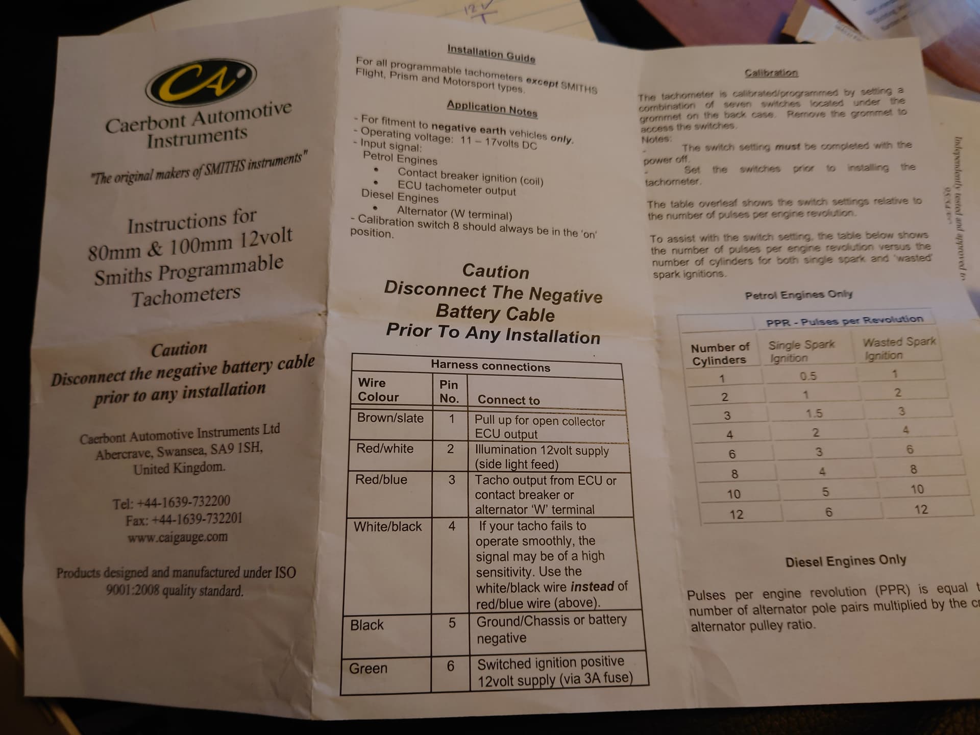
I do see that there is an additional wire in my gauge which is what i need to control.
It says it needs to be pulled up in case of a "Open collector ECU output", no idea what this means.
Any suggestions?
I'm using the 2N5401 which is a PNP transistor.
I might be able to use a mosfet, i have one laying around, do you think that would work?
I don't have a scope as i normally only use thing that are either constantly on or off.
Connect green wire to +12V supply, black wire to 12V ground ( - ), red / blue wire to Arduino output pin, 12V ground to Arduino GND. Use the Tone function to apply a 500Hz signal to the output pin.