Hello guys! My name is Jurgis (George). I am new to this forum so this is kind of hello world message.
Currently I am working on a project in which i want to build a bracelet that could vibrate every single hour for few seconds. I have already built it using Adafruit GEMMA v2 BUT the thing is it won't do anything! I found this amazing DIY here.
Parts I am using:
Adafruit GEMMA v2
PN2222A transistor
510ohm resistor
1N4001 diode
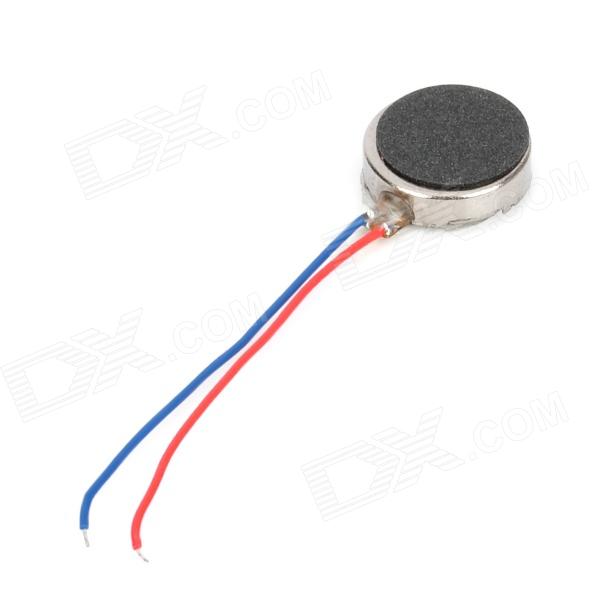
tiny vibrating disc motor
3.7V 160mAh battery
The thing is, i can successfully upload the code from website and when it is disconnected, i can turn it on (green LED goes on) but nothing happens. When i connect board to my PC, motor starts vibrating in short intervals (like it is supposed to do). When uploading, it vibrates too, and when finished uploading, there is one longer vibration and done. After that there are no more vibrations...
I do not have any idea what can be wrong..any help would be amazing. Thanks.
P.S. sorry for my not perfect English (I am from Lithuania)
Please put your code in its own window as seen in other posts. This can be done by placing [code] and [/code] around the code or use the </> icon. This makes it easier for others to read.
const uint32_t           // These may be the only lines you need to edit...
  onTime   =  2 * 1000L, // Vibration motor run time, in milliseconds
  interval = 60 * 1000L; // Time between reminders, in milliseconds
                         // It gets progressively geekier from here...

// Additional power savings can optionally be realized by disabling the
// power-on LED, either by desoldering or by cutting the trace from 3Vo
// on the component side of the board.

// This sketch spends nearly all its time in a low-power sleep state...
#include <avr/power.h>
#include <avr/sleep.h>

// The chip's 'watchdog timer' (WDT) is used to wake up the CPU when needed.
// WDT runs on its own 128 KHz clock source independent of main CPU clock.
// Uncalibrated -- it's "128 KHz-ish" -- thus not reliable for extended
// timekeeping.  To compensate, immediately at startup the WDT is run for
// one maximum-duration cycle (about 8 seconds...ish) while keeping the CPU
// awake, the actual elapsed time is noted and used as a point of reference
// when calculating sleep times.  Still quite sloppy -- the WDT only has a
// max resolution down to 16 ms -- this may drift up to 30 seconds per hour,
// but is an improvement over the 'raw' WDT clock and is adequate for this
// casual, non-medical, non-Mars-landing application.  Alternatives would
// require keeping the CPU awake, draining the battery much quicker.

uint16_t          maxSleepInterval;  // Actual ms in '8-ish sec' WDT interval
volatile uint32_t sleepTime     = 1; // Total milliseconds remaining in sleep
volatile uint16_t sleepInterval = 1; // ms to subtract in current WDT cycle
volatile uint8_t  tablePos      = 0; // Index into WDT configuration table

void setup() {

  // Unused pins can be set to INPUT w/pullup -- most power-efficient state
  pinMode(0, INPUT_PULLUP);
  pinMode(2, INPUT_PULLUP);

  // LED shenanigans.  Rather that setting pin 1 to an output and using
  // digitalWrite() to turn the LED on or off, the internal pull-up resistor
  // (about 10K) is enabled or disabled, dimly lighting the LED with much
  // less current.
  pinMode(1, INPUT);               // LED off to start

  // AVR peripherals that are NEVER used by the sketch are disabled to save
  // tiny bits of power.  Some have side-effects, don't do this willy-nilly.
  // If using analogWrite() to for different motor levels, timer 0 and/or 1
  // must be enabled -- for power efficiency they could be turned off in the
  // ubersleep() function and re-enabled on wake.
  power_adc_disable();             // Knocks out analogRead()
  power_timer1_disable();          // May knock out analogWrite()
  power_usi_disable();             // Knocks out TinyWire library
  DIDR0 = _BV(AIN1D) | _BV(AIN0D); // Digital input disable on analog pins
  // Timer 0 isn't disabled yet...it's needed for one thing first...

  // The aforementioned watchdog timer calibration...
  uint32_t t = millis();                       // Save start time
  noInterrupts();                              // Timing-critical...
  MCUSR &= ~_BV(WDRF);                         // Watchdog reset flag
  WDTCR  =  _BV(WDCE) | _BV(WDE);              // WDT change enable
  WDTCR  =  _BV(WDIE) | _BV(WDP3) | _BV(WDP0); // 8192-ish ms interval
  interrupts();
  while(sleepTime);                            // Wait for WDT
  maxSleepInterval  = millis() - t;            // Actual ms elapsed
  maxSleepInterval += 64;                      // Egyptian constant
  power_timer0_disable();  // Knocks out millis(), delay(), analogWrite()
}

const uint32_t offTime = interval - onTime; // Duration motor is off, ms

void loop() {
  pinMode(1, INPUT_PULLUP); // LED on (using internal pullup)
  ubersleep(onTime);        // Delay while LED/motor on
  pinMode(1, INPUT);        // LED off
  ubersleep(offTime);       // Delay while off
}

// WDT timer operates only in specific intervals based on a prescaler.
// CPU wakes on each interval, prescaler is adjusted as needed to pick off
// the longest setting possible on each pass, until requested milliseconds
// have elapsed.
const uint8_t cfg[] PROGMEM = { // WDT config bits for different intervals
  _BV(WDIE) | _BV(WDP3) |                         _BV(WDP0), // ~8192 ms
  _BV(WDIE) | _BV(WDP3)                                    , // ~4096 ms
  _BV(WDIE) |             _BV(WDP2) | _BV(WDP1) | _BV(WDP0), // ~2048 ms
  _BV(WDIE) |             _BV(WDP2) | _BV(WDP1)            , // ~1024 ms
  _BV(WDIE) |             _BV(WDP2) |             _BV(WDP0), //  ~512 ms
  _BV(WDIE) |             _BV(WDP2)                        , //  ~256 ms
  _BV(WDIE) |                         _BV(WDP1) | _BV(WDP0), //  ~128 ms
  _BV(WDIE) |                         _BV(WDP1)            , //   ~64 ms
  _BV(WDIE) |                                     _BV(WDP0), //   ~32 ms
  _BV(WDIE)                                                  //   ~16 ms
}; // Remember, WDT clock is uncalibrated, times are "ish"

void ubersleep(uint32_t ms) {
  if(ms == 0) return;
  tablePos      = 0;                   // Reset WDT config stuff to
  sleepInterval = maxSleepInterval;    // longest interval to start
  configWDT(ms);                       // Set up for requested time
  set_sleep_mode(SLEEP_MODE_PWR_DOWN); // Deepest sleep mode
  sleep_enable();
  while(sleepTime && (tablePos < sizeof(cfg))) sleep_mode();
  noInterrupts();                      // WDT off (timing critical)...
  MCUSR &= ~_BV(WDRF);
  WDTCR  = 0;
  interrupts();
}

static void configWDT(uint32_t newTime) {
  sleepTime = newTime; // Total sleep time remaining (ms)
  // Find next longest WDT interval that fits within remaining time...
  while(sleepInterval > newTime) {
    sleepInterval /= 2;                          // Each is 1/2 previous
    if(++tablePos >= sizeof(cfg)) return;        // No shorter intervals
  }
  uint8_t bits = pgm_read_byte(&cfg[tablePos]);  // WDT config bits for time
  noInterrupts();                                // Timing-critical...
  MCUSR &= ~_BV(WDRF);
  WDTCR  =  _BV(WDCE) | _BV(WDE);                // WDT change enable
  WDTCR  =  bits;                                // Interrupt + prescale
  interrupts();
}

ISR(WDT_vect) { // Watchdog timeout interrupt
  configWDT(sleepTime - sleepInterval); // Subtract, setup next cycle...
}
So, i have tried both suggestions but none of them work. I then removed everything from the board, uploaded the code and then connected battery. D1 (Red) LED successfully blinks once a minute (just how it is supposed to) but when i connect simple LED or vibrator motor it kind of stops workink, red led stops blinking once a minute too... No idea what is wrong :||
Thank you for answers. Still no luck. But i have discovered some things. First there is the circuit. (sorry for mistakes, first time drawing one).
What i have done:
I have unsoldered everything, then uploaded the code. Everything looks fine, works fine. Then i connected ground, Vout and left D1 free, so i could easily touch and see what happens when LED is on.
So, every 10 seconds LED turns on for 5 seconds. When LED is on, i touch D1 contact with resistor (which connects to tranz and whole circuit should go online) BUT instead LED kind of stops working. When i untouch wire, LED turns on. (Everything happens in those 5 seconds, with every touch LED turns off like it is shortened or sth.)
When measured voltage between Ground and D1, when it is active, U=1.6V, when passive U=0.3V.
Ah, i made a mistake in schematics with TR. It is soldered properly. I have tried various R, but the result is the same. Whenever i touch D1, LED goes off and no vibration
I have just connected LED with R instead of motor and it works just how it is supposed to! Does that mean my motor is not right for this project? (i think it was spare part from old smartphone)
And like 2 minutes ago i broke the contacts of this motor, so i guess i am buying a new one tomorrow
Tomorrow i will try with a new one, and if it won't work i will try using bigger battery. Then i will write here how it went. Thanks for your help, this is amazing
I taught I came up with a new idea until I saw this post.
I am making a youtube video of me making one by scratch. I will also be adding a screen and Bluetooth for smartphone compatibility. I will do some more research and I will record a vid soon.
Thanks for giving me more info.
Regarding your issue, the previous responses are beyond mine.
Soooo, i have connected three AA batteries with new motor but it is still not working. What i noticed is that Voltage when active, across the motor is 0.3V. Any suggestions?
Thank you
JurgisLec:
I have just connected LED with R instead of motor and it works just how it is supposed to! Does that mean my motor is not right for this project? (i think it was spare part from old smartphone)
If still needed, i can do voltage measurements
Did you put the LED in place of the motor (using the Tr) or in place of the Tr and motor.?