I have a load cell of the variety typically used for scales and I am trying to make a scale using an instrumentation amplifier (INA125P) and an Arduino. The instrument amp and the Arduino are well-behaved. I am not getting linearity out of the load cell and I suspect this is because I have physically set it up wrong so I am looking for some advice.
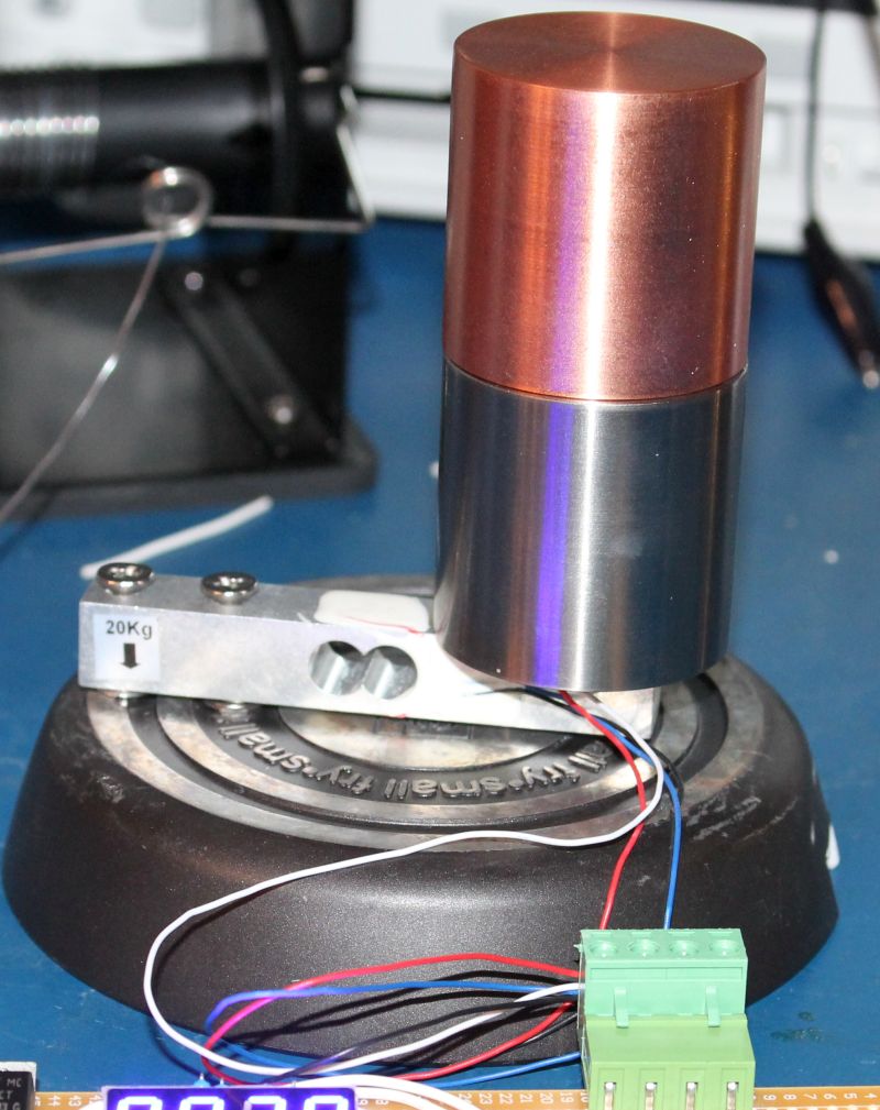
The base is an single egg pan that the Teflon wore out on, so I re-purposed it. It is very rigid. The load cell is tightly screwed into the base with two washers as a shim between the load cell and the base.
The voltages that I am getting out of the load cell, after the amplifier, for the following masses, are:
Test Mass (g)
Amplified Voltage (mV)
Expected ADC Value
Actual ADC Value
0
64.4
(64.4/4995)*1024 = 13
11
469
65.7
(65.7/4995)*1024 = 13
11
1000
87.3
(87.3/4995)*1024 = 18
16
1479
370
(370/4995)*1024 = 76
72
So it doesn't look like it is getting linear until I have 1,000 grams on it. If it even is at that point.
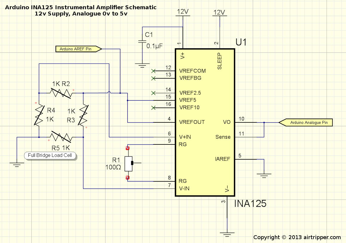
My 5V reference is reading 4.9946V. This is the excitation voltage. The amplifier is set up according to the following schematic: http://airtripper.com/wp-content/uploads/2013/10/arduino-ina125-amplifier-schematic.jpg except that the voltage is 8V, the gain resistor is 10 Ohm, and VREFCOM is tied to ground (I think this is an error in his schematic, the op amp seems to expect that to be tied to ground so that the voltage reference output pins work correctly). Also the Arduino AnalogRead values are not exactly as expected, though they are pretty close so I don't think that is a problem. I don't expect any of this matters, I think I just physically have this load cell set up wrong which is why it is not providing sane voltages.
Are you sure the load (weight) you're applying is always being applied to exactly the same place? if not this could account for the errors.
You also need to 100% sure that the load cells have been attached symmetrically and in accordance with the guidance that came with them, surface prep is very important, as is use the correct adhesive.
OhMyCod:
You also need to 100% sure that the load cells have been attached symmetrically and in accordance with the guidance that came with them, surface prep is very important, as is use the correct adhesive.
You mean strain gauges, right? The load cell is the whole assembled apparatus with the selection of adhesive and surface prep already taken care of. It came as one piece and I didn't have to do any of that. Now, I got it from a cut rate Chinese eBay supplier, but these particular cells seem to be popular and a lot of sellers are selling them. A similar listing:
Does it look like I mounted it right? I have to assume all the adhesive and strain gauge placement is correct.
Thanks for the ADC link, but I know my problem is well before I get to the final conversion. If the voltage is not linearly proportional to the weight I am screwed no matter what ADC I use.
Hi, from repairing instrument amps associated with load cells, they usually are setup pre-loaded.
In your case it looks like 1kg pre load, call that zero and load from there.
Because you are measuring deflection/stress in a cantilever, the fixed point and the position of the load will be important.
In a set of scales they use a platter on a knife edge or pin support on the cell so that the load, not matter how big its base, is applied at the same point of the cell.
As in your picture the load is distributed over the base of the sample, if you move it in or out along the cell the weight indication will change.
Tom......
PS, turn the load cell around, the down arrow should be at the load end.
Wonderful! That is exactly the sort of advice I was looking for. I was worried that I had it backwards but I thought the strain gauges being nearer to the loading point (surface in my case) was preferable because the load should bend the metal there more and therefore and strain the gauges more. Probably a bad move, though. I will be turn that around tomorrow night and and work on mounting some kind of pan with a default mass and set point and see if this clears up the linearity issue. Also, I will check the voltages again after turning it around before deciding on how heavy of a pan I will need to get it into the linear region. Thanks again.
I assume that the load cell is symmetrical? The photo seems to indicate that maybe it's the other end that should loaded? (this is a bit of a long shot)
It appears to be a 20kg load cell, have you checked to see what it's performance is over a greater range? So far you've only tested up to 1.5 kgs.
Finally, how accurate does your application really need to be? If the output values are consistent (albeit not linear), then you might consider using a series of map() functions to create a lookup curve?
TomGeorge:
PS, turn the load cell around, the down arrow should be at the load end.
Thanks again. Once I did that it starts with an offset voltage which I can zero and there is no pre-tensioning needed, it is sensitive to even small weights. It isn't the most sensitive. At these voltages and the 10 bit ADC I seem to get about 1 bit change on the ADC for every 4 grams. Still, if it turns out to be linear that is good enough. I can try it out with a better ADC and see what happens too.
The one problem I have is that the bridge is putting out 0.343mV with no load. This is amplified to 2.24V (G=6531, gain resistor is 10 ohm) by the INA125P. This is no problem to zero in software, but it eats almost half the resolution of the ADC. Is this normal or am I screwing up now in another way? I can turn the gain down, of course, but then I lose sensitivity. Is this a normal trade off? How do you null out a offset voltage like that?