Generating 180 degree phase shifted PWM waves

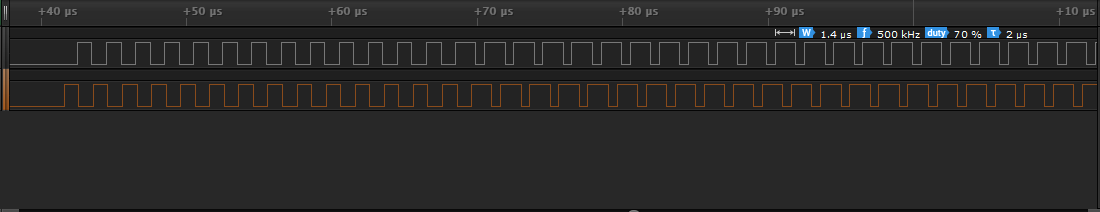
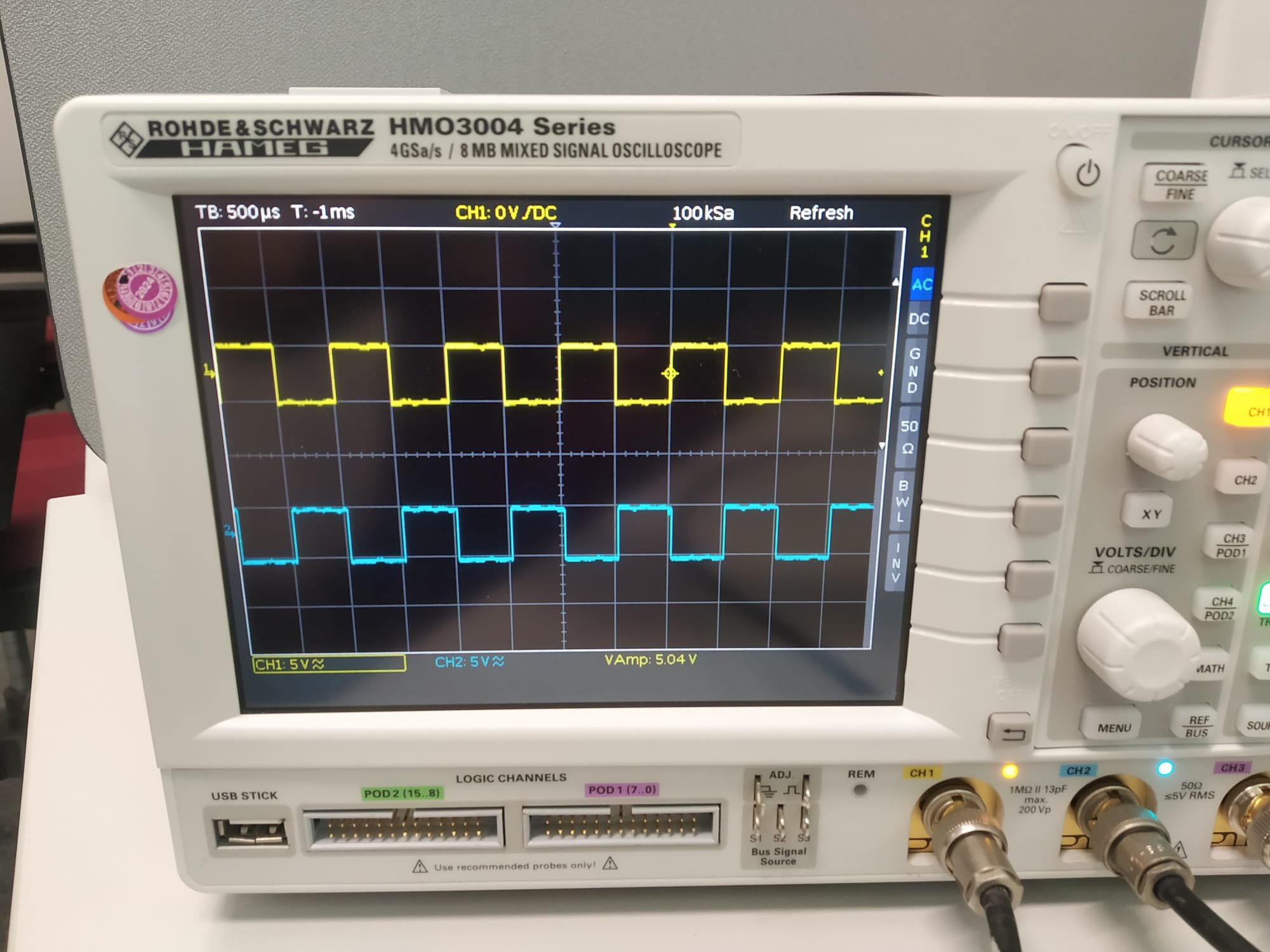
Hi all, I am trying to generate two 180-degree phase-shifted PWM waves. However, my proposed code's wave time period is off by a factor of 8. Also, the code abruptly stops responding for frequencies greater than 200 kHz (Frequency index >7).

My code:

// Define pins for output
const int PIN_9 = 9;
const int PIN_10 = 10;

// Define arrays of frequency and duty cycle values
unsigned long FREQUENCY_VALUES[] = {40000, 50000, 60000, 70000, 80000, 90000, 100000, 200000, 300000, 400000, 500000}; // 100000, 200000, 300000, 400000, 500000, 600000, 700000, 800000, 900000};
unsigned long DUTY_CYCLE_VALUES[] = {10, 20, 30, 40, 50, 60, 70, 80, 90};

// Define the number of frequency and duty cycle values
const int NUM_FREQUENCY_VALUES = sizeof(FREQUENCY_VALUES) / sizeof(FREQUENCY_VALUES[0]);
const int NUM_DUTY_CYCLE_VALUES = sizeof(DUTY_CYCLE_VALUES) / sizeof(DUTY_CYCLE_VALUES[0]);

// Define variables for the frequency and duty cycle index
int frequencyIndex = 1;
int dutyCycleIndex = 4;

// Define variables for the high time and period time in timer cycles
unsigned long periodTime = 0; // duration of a full signal turn
unsigned long highTime = 0;   // duration (pulse width) or hight time of the leading pin as fraction of the periodTime
unsigned long lowTime = 0;    // duration or low time of the leading pin as fraction of the periodTime

// Define a lookup table for the high and period time in timer cycles
unsigned long timerValues[NUM_FREQUENCY_VALUES][NUM_DUTY_CYCLE_VALUES][2];

// Define a function to calculate the high and period time in timer cycles
void calculateTimerValues(unsigned long frequency, unsigned long dutyCycle, unsigned long& highTime, unsigned long& lowTime) {
  // Calculate the period time in timer cycles
  periodTime = (unsigned long)(16000000.0 / (unsigned long)(frequency));

  // Calculate the high time in timer cycles
  highTime = (unsigned long)(periodTime * (unsigned long)(dutyCycle) / 800.0);

  // Calculate the low time in timer cylces
  lowTime = (unsigned long)(periodTime * (unsigned long)(100 - dutyCycle) / 800);
}

// Set up timer1 to generate interrupt at desired frequency and duty cycle
void setupTimerInterrupt() {
  noInterrupts();
  //  Timer/Counter Control Register TCCRnA
  TCCR1A = 0;
  //  Timer/Counter Control Register TCCRnB
  TCCR1B = 0;
  TCNT1 = 0;
  // Select initial low time value depending on index selected.
  OCR1A = timerValues[frequencyIndex][dutyCycleIndex][0];
  //  Waveform Generation Mode bits (WGM)
  TCCR1B |= (1 << WGM12);
  //  Clock Select bits (CS)
  // This should set the prescaler of timer1 to 1, i.e., the highest possible frequency of 16 MHz
  TCCR1B |= (0 << CS12) | (1 << CS11) | (0 << CS10);

  // E.g. this code line sets the prescaler to 8, i.e., the frequency would be 2 MHz -> TCCR1B |= (0 << CS12) | (1 << CS11) | (0 << CS10);
  TIMSK1 |= (1 << OCIE1A);
  interrupts();
}

// ISR for timer1 compare match A interrupt
ISR(TIMER1_COMPA_vect) {
//  pin_phase = false; // current phase (false = 0 degrees, true = 180 degrees)
  static bool phase = false; // current phase (false = 0 degrees, true = 180 degrees)

  uint16_t highTime = (uint16_t)(timerValues[frequencyIndex][dutyCycleIndex][0]); // get high time based on duty cycle
  uint16_t lowTime  = (uint16_t)timerValues[frequencyIndex][dutyCycleIndex][1];   // get low time based on high time and waveform period

//  Serial.print("ISR highTime: ");
//  Serial.println(highTime);
//  Serial.print("ISR lowTime: ");
//  Serial.println(lowTime);

  // Toggle the output pins based on phase
  digitalWrite(PIN_9, phase ? HIGH : LOW);
  digitalWrite(PIN_10, !phase ? HIGH : LOW);
  phase = !phase; // toggle pin phase

  // Update the OCR1A register with the next high or low time value
  OCR1A = phase ? highTime : lowTime;
}

// Setup function
void setup() {
  // Initialize the output pins
  pinMode(PIN_9, OUTPUT);
  pinMode(PIN_10, OUTPUT);

  // Calculate the timer values for each frequency and duty cycle value and store them in the lookup table
  for (int i = 0; i < NUM_FREQUENCY_VALUES; i++) {
    for (int j = 0; j < NUM_DUTY_CYCLE_VALUES; j++) {
      calculateTimerValues(FREQUENCY_VALUES[i], DUTY_CYCLE_VALUES[j], timerValues[i][j][0], timerValues[i][j][1]);}
    }

  // Set up the timer interrupt with the initial frequency and duty cycle values
  setupTimerInterrupt();

  // Initialize the serial communication
  Serial.begin(9600);
  // Make sure the Serial monitor is up and running to avoid strange behavior later. 
  delay(10000);
}

// Loop function
void loop() {
  // Prompt the user to enter a new frequency index
  Serial.println("Enter a new frequency index (0-4): ");
  // Read the input frequency index
  while (!Serial.available());  // wait for user input
  String input = Serial.readStringUntil('\n');   // read string value from serial monitor
  int newFrequencyIndex = input.toInt();
  Serial.println();

  // Prompt the user to enter a new duty cycle high time value:
  Serial.println("Enter a new duty cycle index (0-4): ");
  // Read the input duty cycle index
  while (!Serial.available());  // wait for user input
  input = Serial.readStringUntil('\n');   // read string value from serial monitor
  int newDutyCycleIndex = input.toInt();
  Serial.println();

  // Check if the input values are within the valid range
  if (newFrequencyIndex >= 0 && newFrequencyIndex < NUM_FREQUENCY_VALUES && newDutyCycleIndex >= 0 && newDutyCycleIndex < NUM_DUTY_CYCLE_VALUES) {
    // Update the frequency and duty cycle index
    frequencyIndex = newFrequencyIndex;
    dutyCycleIndex = newDutyCycleIndex;
.
    // Print the new frequency, high time, low time, and total period time to the serial monitor
    double highTimeInMs = (double)(timerValues[frequencyIndex][dutyCycleIndex][0]) / 16000000.0 * 1000.0;
    double lowTimeInMs = (double)(timerValues[frequencyIndex][dutyCycleIndex][1]) / 16000000.0 * 1000.0; 
    double periodTimeInMs = highTimeInMs + lowTimeInMs;
    Serial.print("Frequency: ");
    Serial.print(FREQUENCY_VALUES[frequencyIndex]);
    Serial.print(" Hz, High Time: ");
    Serial.print(highTimeInMs, 5);
    Serial.print(" ms, Low Time: ");
    Serial.print(lowTimeInMs, 5);
    Serial.print(" ms, Period Time: ");
    Serial.print(periodTimeInMs, 5);
    Serial.println(" ms");
  }
} // END void loop()

Search the forum for already discussed and implemented hardware solutions.

That code has a sort of ChatGPT look to it.
You appear to want to vary the frequency in the range 40 to 900 KHz and duty cycle with in from 10 to 90%, want additionally a 180 degree phase shift. Are you free to user other pins than the ones defined in your sketch ?
What board are you using ?

Hi, I am using Arduino Uno right now. All the pins are also free.

These comments are wrong. Did you write them? I did not look any further to see if there are other code errors.

Avoid use of Strings. They cause program crashes and unpredictable behavior on Arduinos.

Apart from the prescaler problem already mentioned, which could explain the "factor of 8" problem, you also have a problem here. digitalWrite() takes a few microseconds to execute. Per wave, digitalWrite() is called 4 times. Also an ISR call takes a few microseconds. This will limit the maximum frequency and accuracy of the duty cycle. Under these circumstances, the 200 kHz you say that you have achieved actually sounds high. You'd best look a fast PWM mode on timer 1, which directly manipulates the pins. You may have to use a transistor or similar to provide the inverted signal. You may get some improvement using direct port manipulation instead of digitalWrite() but nowhere near the 900 kHz mentioned in the code.

Have you an oscilloscope or logic analyser to check the output?

EDIT

Here is an example of using timer 1 in fast PWM mode with control over both the frequency and the duty cycle: Gammon Forum : Electronics : Microprocessors : Timers and counters

The core of it is very simple and note that there is no ISR and no explicit pin manipulation.

You said the program becomes unresponsive on reaching a certain frequency. Once the interrupts take 100% of CPU capacity, the loop() is no longer serviced.

Makes sense. I'll again check my output using an oscilloscope. Thanks for you feedback.

To get the 180° phase shift you will need to use two timers. There is an option to synchronize timers so by setting the TCNT of one timer to zero and getting the TCNT of the other to TOP/2 you can start them 180° out of phase. Since they run off the same system clock they should stay in sync.

Because there is only one 16-bit timer you will be limited to 8-bit PWM. I think you might have trouble with prescale since Timer2 and Timer1 have different choices of prescale factors:

Timer1: 1, 8,     64,      256, 1024
Timer2: 1, 8, 32, 64, 128, 256, 1024

Try this. It compiles for Arduino UNO without error but I have not checked the outputs (Pin 10 and Pin 5)

// Generating 180* out-of-phase Variable-Frequency PWM on
// Timer1 and Timer2 of an Arduino UNO (Pins 10 and 5)
// Written April 29th, 2023 by John Wasser

uint8_t TimerTOP;  // Value from 0 to 255
byte PercentPWM = 50;  // Default to 50% duty cycle

void FPWM180Begin()
{
  pinMode(10, OUTPUT); // OC1B
  pinMode(5, OUTPUT); // OC2B
  
  // Stop Timer/Counter1
  TCCR1A = 0;  // Timer/Counter1 Control Register A
  TCCR1B = 0;  // Timer/Counter1 Control Register B
  TIMSK1 = 0;  // Timer/Counter1 Interrupt Mask Register

  // Stop Timer/Counter2
  TCCR2A = 0;  // Timer/Counter2 Control Register A
  TCCR2B = 0;  // Timer/Counter2 Control Register B
  TIMSK2 = 0;  // Timer/Counter2 Interrupt Mask Register

  // Set Timer/Counter1 to WGM 15: (Fast PWM with TOP in OCR1A)
  TCCR1A |= _BV(WGM11) | _BV(WGM10);
  TCCR1B |= _BV(WGM13) | _BV(WGM12);

  // Set Timer/Counter2 to WGM 7 (Fast PWM with TOP in OCR2A)
  TCCR2A |= _BV(WGM11) | _BV(WGM10);
  TCCR2B |= _BV(WGM12);

  // Enable normal PWM on OC1B (10) and OC2B (5)
  TCCR1A |= _BV(COM1B1);  // Norml PWM on Pin 10
  TCCR2A |= _BV(COM2B1);  // Norml PWM on Pin 5


  FPWM180SetFrequency(1000);  // Default to 1 kHz
}

bool FPWM180SetFrequency(uint16_t frequency)
{
  byte prescaleBits1; // 1, 2, 3, 4, 5
  byte prescaleBits2; // 1, 2, 4, 6, 7
  uint16_t prescaleFactor;  // 1, 8, 64, 256, 1024
  uint32_t top32;

  // Clear the three clock select bits to stop the timers
  TCCR1B &= ~(_BV(CS12) | _BV(CS11) | _BV(CS10));
  TCCR2B &= ~(_BV(CS22) | _BV(CS21) | _BV(CS20));
  
  // Find the smallest prescale factor that will
  // fit the 8-bit TOP value.
  // frequency = F_CPU / (prescale * (TOP + 1))
  // TOP = (F_CPU / (prescale * frequency)) - 1;

  prescaleBits1 = 1;
  prescaleBits2 = 1;
  prescaleFactor = 1;
  top32 = F_CPU / (prescaleFactor * frequency) - 1;
  if (top32 > 255ul) // Too many clocks to count in 8 bits?
  {
    prescaleBits1 = 2;
    prescaleBits2 = 2;
    prescaleFactor = 8;
    top32 = F_CPU / (prescaleFactor * frequency) - 1;
    if (top32 > 255ul) // Too many clocks to count in 8 bits?
    {
      prescaleBits1 = 3;
      prescaleBits2 = 4;
      prescaleFactor = 64;
      top32 = F_CPU / (prescaleFactor * frequency) - 1;
      if (top32 > 255ul) // Too many clocks to count in 8 bits?
      {
        prescaleBits1 = 4;
        prescaleBits2 = 6;
        prescaleFactor = 256; // Only used for 1 Hz
        top32 = F_CPU / (prescaleFactor * frequency) - 1;
        if (top32 > 255ul) // Too many clocks to count in 8 bits?
        {
          prescaleBits1 = 5;
          prescaleBits2 = 7;
          prescaleFactor = 1024;
          top32 = F_CPU / (prescaleFactor * frequency) - 1;
          if (top32 > 255ul) // Too many clocks to count in 8 bits?
          {
            return false;
          }
        }
      }
    }
  }

  Serial.print("Freq: ");
  Serial.print(frequency);
  Serial.print(" prescale: ");
  Serial.print(prescaleFactor);
  Serial.print(" TOP: ");
  Serial.println(top32);

  if (top32 < 16)
    return false; // Require at least 16 levels of PWM

  TimerTOP = top32;

  OCR1A = TimerTOP;
  OCR2A = TimerTOP;

  // Since TOP might have changed...
  OCR1B = (PercentPWM * (uint32_t)TimerTOP) / 100;
  OCR2B = (PercentPWM * (uint32_t)TimerTOP) / 100;

   // Freeze the prescale counters on Timer1 and Timer2
  GTCCR = _BV(TSM) | _BV(PSRASY);

  TCNT1 = 0;
  TCNT2 = TimerTOP / 2;  // 180° out of phase

  TCCR1B |= prescaleBits1; // Set clock prescale bits
  TCCR2B |= prescaleBits2; // Set clock prescale bits

  GTCCR = 0;  // Unfreeze the prescale counters
  return true;
}

void FPWM180SetDutyCyclePercentage(byte percent)
{
  PercentPWM = min(percent, 100);
  OCR1B = (PercentPWM * (uint32_t)TimerTOP) / 100;
  OCR2B = (PercentPWM * (uint32_t)TimerTOP) / 100;
}


void setup()
{
  Serial.begin(115200);

  FPWM180Begin();  // Start output at 1000 Hz, 50% duty cycle
}

void loop()
{
  // Call FPWM180SetFrequency(uint16_t frequency) any time to change the output frequency
  // Call FPWM180SetDutyCyclePercentage(byte percent) at any time to change duty cycle
}

How that? 180° phase shift means an inverted signal which can be generated by the second channel of a timer by simply setting its "inverse output" bit.

In phase correct modes it even is possible to insert gaps between the signals, as required to control complementary transistors in a H-bridge.

Also follow my suggestion in #2 for easy implementations.

ONLY for a 50% Duty Cycle signal (Square Wave). For duty cycles less than 50% the pulses are disjoint. For duty cycles greater than 50% the pulses will overlap

I must admit I was unsure about what the OP meant by 180 degree phase shift.
The code appears to suggest that he meant inversion as here:

digitalWrite(PIN_9, phase ? HIGH : LOW);
digitalWrite(PIN_10, !phase ? HIGH : LOW);

I suppose he could also have meant the waveform on pin 10 is shifted by 0.5/f seconds from that on pin 9 (if I have got my maths right).
I'm still looking at @johnwasser's code to see if there are any other possible interpretations.

Fast PWM allows only the pin connected to the "B" side of the timer to be used (in the cases I have tried).

On Timer1 if you use WGM 4, 9, 11, or 15 where OCR1A is used for TOP.
On Timer2 if you use WGM 2, 5, or 7 where OCR2A is used for TOP.
For other PWM modes you can have PWM on the A pin.

For Timer1 you can use WGM 14 instead of WGM15. It's also FastPWM but uses the ICR1 register for TOP. That allows the PWM frequency to be set AND the use of PWM on both pins.

OK. Thanks. I've normally had this experience with timers 0 and 2 and lots of debugging until I discovered the problem.

I've just tried your code in post #8 because I am curious to see how it works. I just happen to have a Uno and logic analyser on may desk.
I got this on the serial monitor:

19:40:25.948 -> FFreq: 1000 prescale: 64 TOP: 249

but this on the logic analyser, that is pin 10 is OK but no visible waveform on pin 5. I don't think that I have made a mistake because I have tried another sketch which sends timer output to pin 5 and that works:

I guess it's time to drag out my

oscilloscope. :frowning:

Confirmed: No signal on 5.

Found the mistake. Pin 5 is OC0B. OC2B is on Pin 3. Have to move the pinMode(5, OUTPUT); to pinMode(3, OUTPUT); to enable the output drivers.

// Generating 180* out-of-phase Variable-Frequency PWM on
// Timer1 and Timer2 of an Arduino UNO (Pins 10 and 3)
// Written April 29th, 2023 by John Wasser

uint8_t TimerTOP;  // Value from 0 to 255
byte PercentPWM = 50;  // Default to 50% duty cycle

void FPWM180Begin()
{
  pinMode(10, OUTPUT); // OC1B
  pinMode(3, OUTPUT); // OC2B
  
  // Stop Timer/Counter1
  TCCR1A = 0;  // Timer/Counter1 Control Register A
  TCCR1B = 0;  // Timer/Counter1 Control Register B
  TIMSK1 = 0;  // Timer/Counter1 Interrupt Mask Register

  // Stop Timer/Counter2
  TCCR2A = 0;  // Timer/Counter2 Control Register A
  TCCR2B = 0;  // Timer/Counter2 Control Register B
  TIMSK2 = 0;  // Timer/Counter2 Interrupt Mask Register

  // Set Timer/Counter1 to WGM 15: (Fast PWM with TOP in OCR1A)
  TCCR1A |= _BV(WGM11) | _BV(WGM10);
  TCCR1B |= _BV(WGM13) | _BV(WGM12);

  // Set Timer/Counter2 to WGM 7 (Fast PWM with TOP in OCR2A)
  TCCR2A |= _BV(WGM11) | _BV(WGM10);
  TCCR2B |= _BV(WGM12);

  // Enable normal PWM on OC1B (10) and OC2B (5)
  TCCR1A |= _BV(COM1B1);  // Norml PWM on Pin 10
  TCCR2A |= _BV(COM2B1);  // Norml PWM on Pin 3


  FPWM180SetFrequency(1000);  // Default to 1 kHz
}

bool FPWM180SetFrequency(uint16_t frequency)
{
  byte prescaleBits1; // 1, 2, 3, 4, 5
  byte prescaleBits2; // 1, 2, 4, 6, 7
  uint16_t prescaleFactor;  // 1, 8, 64, 256, 1024
  uint32_t top32;

  // Clear the three clock select bits to stop the timers
  TCCR1B &= ~(_BV(CS12) | _BV(CS11) | _BV(CS10));
  TCCR2B &= ~(_BV(CS22) | _BV(CS21) | _BV(CS20));
  
  // Find the smallest prescale factor that will
  // fit the 8-bit TOP value.
  // frequency = F_CPU / (prescale * (TOP + 1))
  // TOP = (F_CPU / (prescale * frequency)) - 1;

  prescaleBits1 = 1;
  prescaleBits2 = 1;
  prescaleFactor = 1;
  top32 = F_CPU / (prescaleFactor * frequency) - 1;
  if (top32 > 255ul) // Too many clocks to count in 8 bits?
  {
    prescaleBits1 = 2;
    prescaleBits2 = 2;
    prescaleFactor = 8;
    top32 = F_CPU / (prescaleFactor * frequency) - 1;
    if (top32 > 255ul) // Too many clocks to count in 8 bits?
    {
      prescaleBits1 = 3;
      prescaleBits2 = 4;
      prescaleFactor = 64;
      top32 = F_CPU / (prescaleFactor * frequency) - 1;
      if (top32 > 255ul) // Too many clocks to count in 8 bits?
      {
        prescaleBits1 = 4;
        prescaleBits2 = 6;
        prescaleFactor = 256; // Only used for 1 Hz
        top32 = F_CPU / (prescaleFactor * frequency) - 1;
        if (top32 > 255ul) // Too many clocks to count in 8 bits?
        {
          prescaleBits1 = 5;
          prescaleBits2 = 7;
          prescaleFactor = 1024;
          top32 = F_CPU / (prescaleFactor * frequency) - 1;
          if (top32 > 255ul) // Too many clocks to count in 8 bits?
          {
            return false;
          }
        }
      }
    }
  }

  Serial.print("Freq: ");
  Serial.print(frequency);
  Serial.print(" prescale: ");
  Serial.print(prescaleFactor);
  Serial.print(" TOP: ");
  Serial.println(top32);

  if (top32 < 16)
    return false; // Require at least 16 levels of PWM

  TimerTOP = top32;

  OCR1A = TimerTOP;
  OCR2A = TimerTOP;

  // Since TOP might have changed...
  OCR1B = (PercentPWM * (uint32_t)TimerTOP) / 100;
  OCR2B = (PercentPWM * (uint32_t)TimerTOP) / 100;

   // Freeze the prescale counters on Timer1 and Timer2
  GTCCR = _BV(TSM) | _BV(PSRASY);

  TCNT1 = 0;
  TCNT2 = TimerTOP / 2;  // 180° out of phase

  TCCR1B |= prescaleBits1; // Set clock prescale bits
  TCCR2B |= prescaleBits2; // Set clock prescale bits

  GTCCR = 0;  // Unfreeze the prescale counters
  return true;
}

void FPWM180SetDutyCyclePercentage(byte percent)
{
  PercentPWM = min(percent, 100);
  OCR1B = (PercentPWM * (uint32_t)TimerTOP) / 100;
  OCR2B = (PercentPWM * (uint32_t)TimerTOP) / 100;
}


void setup()
{
  Serial.begin(115200);

  FPWM180Begin();  // Start output at 1000 Hz, 50% duty cycle
}

void loop()
{
  // Call FPWM180SetFrequency(uint16_t frequency) any time to change the output frequency
  // Call FPWM180SetDutyCyclePercentage(byte percent) at any time to change duty cycle
}

Looks like it can cover the desired range of frequencies. I think it can go as low as 62 Hz and as high as 1 MHz.

Freq: 1000 prescale: 64 TOP: 249
Freq: 40000 prescale: 8 TOP: 49
Freq: 50000 prescale: 8 TOP: 39
Freq: 60000 prescale: 8 TOP: 32
Freq: 70000 prescale: 1 TOP: 227
Freq: 80000 prescale: 1 TOP: 199
Freq: 90000 prescale: 1 TOP: 176
Freq: 100000 prescale: 1 TOP: 159
Freq: 200000 prescale: 1 TOP: 79
Freq: 300000 prescale: 1 TOP: 52
Freq: 400000 prescale: 1 TOP: 39
Freq: 500000 prescale: 1 TOP: 31

Oh Yes. OC2B is physical pin 5 but actually arduino pin 3. I guess you changed frequency to uint32_t.

After 5 seconds, I changed from the default 1000Hz / 50% duty cycle to 500,000Hz / 70% duty cycle.

void loop()
{
  static bool run = true ;
  if ( millis() > 5000 && run ) {
    run = false ;
    FPWM180SetFrequency(500000UL) ; // any time to change the output frequency
    FPWM180SetDutyCyclePercentage( 70 ) ; //  at any time to change duty cycle
  }
}

The frequency changed OK. The duty cycle and phase shift don't look so good

. . . but seem to improve slowly !!

In a Phase Correct PWM mode the output pulses center around TOP (or BOTTOM if you like). 180° shift means inverted signal and complementary duty cycle on the second channel.

That should be: GTCCR = _BV(TSM) | _BV(PSRASY) | _BV(PSRSYNC);`
PSRASY only does Timer2, PSRSYNC does Timer1 and Timer0.

it is possible that the calculations based on TimerTOP should be based on (TimerTOP+1).

Clearly, there is still some scope for discussion about what a 180 degree phase shift means in the context of a PWM signal. In the case of sine wave there is no discussion. But what if the OP had asked for a 90 degree phase shift for his PWM signal? I don't think a simple inversion would have handled it.

Anyway, I've applied the latest changes

and since I have got the hardware still sitting on my desk, I gave it a spin. It looks good and clean.

Start with default 1kHz 50%

Transition to 500kHz 70% part 1

Transition to 500kHz 70% part 2

Transition to 500kHz 70% part 3

Final 500kHz 70%

Good work!

Dear @johnwasser & @6v6gt , thank you so much for your solution and testing. I couldn't have asked for more. However, when I am checking it with my oscilloscope, the switch is not happening from 1000 Hz to 500kHz. I fear there might be some issue with my oscilloscope circuit. I am using a setup like this:

1000 Hz coming up correctly...

After that, going static...

My code was:

// Generating 180* out-of-phase Variable-Frequency PWM on
// Timer1 and Timer2 of an Arduino UNO (Pins 10 and 3)
// Written April 29th, 2023 by John Wasser

uint8_t TimerTOP;  // Value from 0 to 255
byte PercentPWM = 50;  // Default to 50% duty cycle

void FPWM180Begin()
{
  pinMode(10, OUTPUT); // OC1B
  pinMode(3, OUTPUT); // OC2B
  
  // Stop Timer/Counter1
  TCCR1A = 0;  // Timer/Counter1 Control Register A
  TCCR1B = 0;  // Timer/Counter1 Control Register B
  TIMSK1 = 0;  // Timer/Counter1 Interrupt Mask Register

  // Stop Timer/Counter2
  TCCR2A = 0;  // Timer/Counter2 Control Register A
  TCCR2B = 0;  // Timer/Counter2 Control Register B
  TIMSK2 = 0;  // Timer/Counter2 Interrupt Mask Register

  // Set Timer/Counter1 to WGM 15: (Fast PWM with TOP in OCR1A)
  TCCR1A |= _BV(WGM11) | _BV(WGM10);
  TCCR1B |= _BV(WGM13) | _BV(WGM12);

  // Set Timer/Counter2 to WGM 7 (Fast PWM with TOP in OCR2A)
  TCCR2A |= _BV(WGM11) | _BV(WGM10);
  TCCR2B |= _BV(WGM12);

  // Enable normal PWM on OC1B (10) and OC2B (5)
  TCCR1A |= _BV(COM1B1);  // Norml PWM on Pin 10
  TCCR2A |= _BV(COM2B1);  // Norml PWM on Pin 3


  FPWM180SetFrequency(1000);  // Default to 1 kHz
}

bool FPWM180SetFrequency(uint16_t frequency)
{
  byte prescaleBits1; // 1, 2, 3, 4, 5
  byte prescaleBits2; // 1, 2, 4, 6, 7
  uint16_t prescaleFactor;  // 1, 8, 64, 256, 1024
  uint32_t top32;

  // Clear the three clock select bits to stop the timers
  TCCR1B &= ~(_BV(CS12) | _BV(CS11) | _BV(CS10));
  TCCR2B &= ~(_BV(CS22) | _BV(CS21) | _BV(CS20));
  
  // Find the smallest prescale factor that will
  // fit the 8-bit TOP value.
  // frequency = F_CPU / (prescale * (TOP + 1))
  // TOP = (F_CPU / (prescale * frequency)) - 1;

  prescaleBits1 = 1;
  prescaleBits2 = 1;
  prescaleFactor = 1;
  top32 = F_CPU / (prescaleFactor * frequency) - 1;
  if (top32 > 255ul) // Too many clocks to count in 8 bits?
  {
    prescaleBits1 = 2;
    prescaleBits2 = 2;
    prescaleFactor = 8;
    top32 = F_CPU / (prescaleFactor * frequency) - 1;
    if (top32 > 255ul) // Too many clocks to count in 8 bits?
    {
      prescaleBits1 = 3;
      prescaleBits2 = 4;
      prescaleFactor = 64;
      top32 = F_CPU / (prescaleFactor * frequency) - 1;
      if (top32 > 255ul) // Too many clocks to count in 8 bits?
      {
        prescaleBits1 = 4;
        prescaleBits2 = 6;
        prescaleFactor = 256; // Only used for 1 Hz
        top32 = F_CPU / (prescaleFactor * frequency) - 1;
        if (top32 > 255ul) // Too many clocks to count in 8 bits?
        {
          prescaleBits1 = 5;
          prescaleBits2 = 7;
          prescaleFactor = 1024;
          top32 = F_CPU / (prescaleFactor * frequency) - 1;
          if (top32 > 255ul) // Too many clocks to count in 8 bits?
          {
            return false;
          }
        }
      }
    }
  }

  Serial.print("Freq: ");
  Serial.print(frequency);
  Serial.print(" prescale: ");
  Serial.print(prescaleFactor);
  Serial.print(" TOP: ");
  Serial.println(top32);

  if (top32 < 16)
    return false; // Require at least 16 levels of PWM

  TimerTOP = top32;

  OCR1A = TimerTOP;
  OCR2A = TimerTOP;

  // Since TOP might have changed...
  OCR1B = (PercentPWM * (uint32_t)TimerTOP) / 100;
  OCR2B = (PercentPWM * (uint32_t)TimerTOP) / 100;

  // Freeze the prescale counters on Timer1 and Timer2
  GTCCR = _BV(TSM) | _BV(PSRASY) | _BV(PSRSYNC);

  TCNT1 = 0;
  TCNT2 = TimerTOP / 2;  // 180° out of phase

  TCCR1B |= prescaleBits1; // Set clock prescale bits
  TCCR2B |= prescaleBits2; // Set clock prescale bits

  GTCCR = 0;  // Unfreeze the prescale counters
  return true;
}

void FPWM180SetDutyCyclePercentage(byte percent)
{
  PercentPWM = min(percent, 100);
  OCR1B = (PercentPWM * (uint32_t)TimerTOP) / 100;
  OCR2B = (PercentPWM * (uint32_t)TimerTOP) / 100;
}


void setup()
{
  Serial.begin(115200);

  FPWM180Begin();  // Start output at 1000 Hz, 50% duty cycle
}

void loop()
{
  static bool run = true ;
  if ( millis() > 5000 && run ) {
    run = false ;
    FPWM180SetFrequency(500000UL) ; // any time to change the output frequency
    FPWM180SetDutyCyclePercentage( 70 ) ; //  at any time to change duty cycle
  }
}