Hello!
Can someone help me to get the low pass filter into my arduino sketch? Maybe without libarys, simply c++ code?
DC Removal
There are two things you should notice in the graph (figure 3):
- The graph is oscillating slightly
- It has a DC offset of 50 000 units
To properly be able to read the heart rate and SaO2 we need to remove the DC signal and leave only the AC part.
It is actually very simple and can be done using these two equations:
w(t)=x(t)+∝∗w(t−1)
y(t)=w(t)−w(t−1)
y(t): is the output of the filter
x(t): current input/value
w(t): intermediate value, acts like the history of the DC value
α: is the response constant of the filter
If α = 1 then everything passes through
If α = 0 then nothing passes through
for DC removal you want the α as rather close to 1. I’ll be using α = 0.95If you want to read more about DC removal, here is a good tutorial and much more detailed description of how it functions: Everyday DSP for Programmers: DC and Impulsive Noise Removal
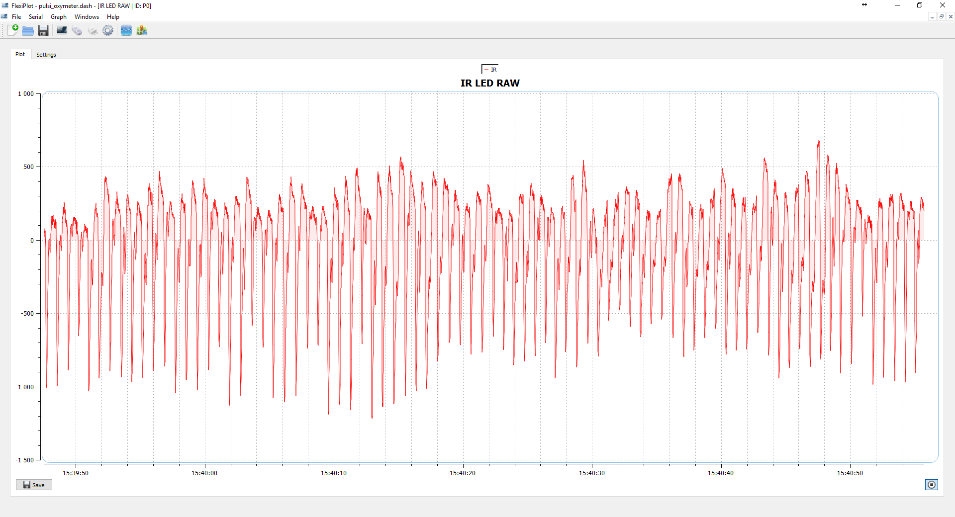
Here is the filter implemented in a code:
struct fifo_t {
  uint16_t rawIR;
  uint16_t rawRed;
};
dcFilter_t MAX30100::dcRemoval(float x, float prev_w, float alpha)
{
  dcFilter_t filtered;
  filtered.w = x + alpha * prev_w;
  filtered.result = filtered.w - prev_w;

  return filtered;
}
Once, we pass the signal through the DC removal filter, we should get a signal similar to the one in figure 4: