** ##EDIT: Finally, all the images are replaced with low resolution images, sorry for the inconvenience.**
Hi, Guys. This my first time with nRF24L01+ modules. But, Kind of getting strange thing like only receiving burst erroneous output in the serial monitor of receiving side, while powering down the receiver, otherwise it stays blank. So, could anyone help me with this ?
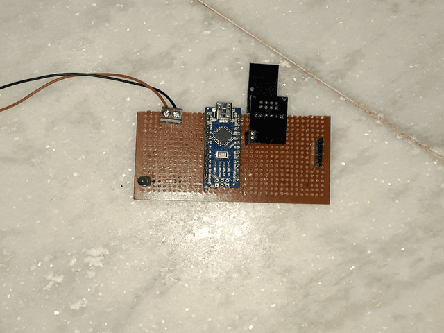
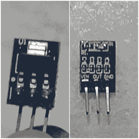
Here below, i've explained the problem in detail with connection diagrams, source and all....
the code i'm using is simple oneway transmission from the tutorial
tx code
// SimpleTx - the master or the transmitter

#include <SPI.h>
#include <nRF24L01.h>
#include <RF24.h>


#define CE_PIN   9
#define CSN_PIN 10

const byte slaveAddress[5] = {'R','x','A','A','A'};


RF24 radio(CE_PIN, CSN_PIN); // Create a Radio

char dataToSend[10] = "Message 0";
char txNum = '0';


unsigned long currentMillis;
unsigned long prevMillis;
unsigned long txIntervalMillis = 1000; // send once per second


void setup() {

    Serial.begin(9600);

    Serial.println("SimpleTx Starting");

    radio.begin();
    radio.setDataRate( RF24_250KBPS );
    radio.setRetries(3,5); // delay, count
    radio.openWritingPipe(slaveAddress);
}

//====================

void loop() {
    currentMillis = millis();
    if (currentMillis - prevMillis >= txIntervalMillis) {
        send();
        prevMillis = millis();
    }
}

//====================

void send() {

    bool rslt;
    rslt = radio.write( &dataToSend, sizeof(dataToSend) );
        // Always use sizeof() as it gives the size as the number of bytes.
        // For example if dataToSend was an int sizeof() would correctly return 2

    Serial.print("Data Sent ");
    Serial.print(dataToSend);
    if (rslt) {
        Serial.println("  Acknowledge received");
        updateMessage();
    }
    else {
        Serial.println("  Tx failed");
    }
}

//================

void updateMessage() {
        // so you can see that new data is being sent
    txNum += 1;
    if (txNum > '9') {
        txNum = '0';
    }
    dataToSend[8] = txNum;
}
Rx code
// SimpleRx - the slave or the receiver

#include <SPI.h>
#include <nRF24L01.h>
#include <RF24.h>

#define CE_PIN   9
#define CSN_PIN 10

const byte thisSlaveAddress[5] = {'R','x','A','A','A'};

RF24 radio(CE_PIN, CSN_PIN);

char dataReceived[10]; // this must match dataToSend in the TX
bool newData = false;

//===========

void setup() {

    Serial.begin(9600);

    Serial.println("SimpleRx Starting");
    radio.begin();
    radio.setDataRate( RF24_250KBPS );
    radio.openReadingPipe(1, thisSlaveAddress);
    radio.startListening();
}

//=============

void loop() {
    getData();
    showData();
}

//==============

void getData() {
    if ( radio.available() ) {
        radio.read( &dataReceived, sizeof(dataReceived) );
        newData = true;
    }
}

void showData() {
    if (newData == true) {
        Serial.print("Data received ");
        Serial.println(dataReceived);
        newData = false;
    }
}
The transmitter serial port is showing desired ouput, but receiver is not showing any received data, it shows a bunch of output like below, when i powered off the receiver
Full marks for giving lots of detail but you have posted very high resolution images and my internet connection is so slow tonight that I have had to give up waiting for them to load. 640 x 480 resolution images are usually fine and much kinder to those of us with slow or expensive internet connections.
Robin2:
Full marks for giving lots of detail but you have posted very high resolution images and my internet connection is so slow tonight that I have had to give up waiting for them to load. 640 x 480 resolution images are usually fine and much kinder to those of us with slow or expensive internet connections.
I'll try again tomorrow,
...R
ok,I'm waiting.
In my future posts, I'll post the appropriate quality of images.
Thank you
It's still incredibly slow. I won't be opening this Thread again for at least a week (when I may have a better internet connection). Unless, of course, you decide to replace all the images with lower resolution versions,
Looking at the photo in Reply #9 I reckon the high-power nRF24 is too close to the other one. Try them at a distance of 3 metres or more.
Robin2:
It's still incredibly slow. I won't be opening this Thread again for at least a week (when I may have a better internet connection). Unless, of course, you decide to replace all the images with lower resolution versions,
Looking at the photo in Reply #9 I reckon the high-power nRF24 is too close to the other one. Try them at a distance of 3 metres or more.
...R
oh sorry for that, I'll replace all the images with low resolution ones. And I also thinking about increasing the distance between them since I saw the same suggestion, u have given to someone in one discussion of this same problem. I'll definitely do this and i will reply if I have any improvements, Thank you : )
Robin2:
It's still incredibly slow. I won't be opening this Thread again for at least a week (when I may have a better internet connection). Unless, of course, you decide to replace all the images with lower resolution versions
Uploaded new low - res images, i hope its ok now for all to see this
Robin2:
If you have a second low-power nRF24 it would probably be a good idea to prove that communication works with it before trying the high-power version.
...R
ok I understood, I don't have, I need to buy, I'll update, if it works
Nagarajan492:
ok I understood, I don't have, I need to buy, I'll update, if it works
It is always a good idea to have a few spares for wireless modules as the only way to figure out if one is damaged is by trying a good one in its place.
ya I understood I already have one low power version extra, while I checking the spi Communication with the arduino using the check connection program u provided, but this one fails in that, so I have only 2 left passed that.(the above ones )
Because of these lockdown, these materials are not available now in my area, so let see,
I'll increase the range and test and
Also if I could get new one, I'll replace it with high power version,
And I also forgot to thank you for providing such a nice tutorial on these nrf24L01+, because with those and some google search, I now learned to look out library source code and what are all the other functions I can work with this, etc.