Ghosting effect with 4x4x4 LED-Cube

BJT can be used in parallel, this is done by adding emitter resistors.
MOSFET works fine in parallel when used in switching applications, but is often problematic in analog applications. Even a single MOSFET can be problematic in high power analog, this can be seen from the SOA specification.

With the ghosting, have it been tried to step slowly through the phases (a few seconds for each step) to check that everything works correctly at DC levels?

BJT can be used in parallel, this is done by adding emitter resistors.

Yer yer yer. Thought you might say that. That is what all the engineers on the ill fated projects said. Simply it does not work in practice. Been there got the tee shirts.

MOSFET works fine in parallel when used in switching applications, but is often problematic in analog applications.

Good job we are not talking about analogue circuits then isn’t it.

With the ghosting, have it been tried to step slowly through the phases (a few seconds for each step) to check that everything works correctly at DC levels?

Now for a change that is a good suggestion.

Grumpy_Mike:
Yer yer yer. Thought you might say that. That is what all the engineers on the ill fated projects said. Simply it does not work in practice. Been there got the tee shirts.

Just because you saw a failed project does not mean it wont work. There exist lots of projects with many BJT's in parallel, I have been involved in some 60 & 100A DC supplys, that used many 2N3055 in parallel . They worked perfectly.
Before MOSFET and switching parallel BJTs was successfully used in a lot of applications.

Just because you saw a failed project does not mean it wont work

No I didn’t just see one, I was involved in several but not as lead engineer.

By the time you have enough resistance to make the idea work you are switching less than half the current thus negating the effects of sharing. The results were always unstable.

There exist lots of projects with many BJT's in parallel, I have been involved in some 60 & 100A DC supplys, that used many 2N3055 in parallel . They worked perfectly.

Well bully for you. It is still utterly useless to suggest to a beginner that you can do this, and especially when he asked what he did in the context of what he did. But hey I have met many engineers like you in the past. Never been impressed with them.

The point here is that we are not implementing an analog amplifier where wastage of power (voltage) in the amplifying elements is part of the process, but a switching system where what is important is that it switches with a very low internal resistance and voltage drop.

This is important for two reasons, operating with a 5 V supply means that fractions of a volt become significant, and it is highly undesirable that the voltage changes depending on the load, which is to say the number of parallel LEDs illuminated at any one time.

Considerations of "current distribution" over multiple devices are thus moot. :astonished:

Grumpy_Mike:
By the time you have enough resistance to make the idea work you are switching less than half the current thus negating the effects of sharing. The results were always unstable.
Well bully for you. It is still utterly useless to suggest to a beginner that you can do this, and especially when he asked what he did in the context of what he did. But hey I have met many engineers like you in the past. Never been impressed with them.

It was silly starting on BJT's, for switching applications there is very little reason to use them today.

One way to avoid ghosting:

Take OE high
Clock a all off pattern out (Both directions) and latch.
Take OE low shortly (delayMicroseconds(10)), this will turn the current MOS transistor off.
Take OE high
Clock the next pattern out and latch.
Take OE low again for the frame time.

If there is any ghosting with this, it is a hardware problem, maybe ground bounce or it is not ghosting but valid but unwanted frame data.

Paul__B:
Not the current limit of the transistor as such, but you would need 56 mA to drive the transistors into saturation, and where are you going to get 56 mA?

Putting BJTs into saturation will cause ghosting as they do not turn off cleanly. Something I learned some 45 years ago!

I didn't think of this...Ultimately this means that I need to go back to MOSFETs for a bigger cube, unless I split it like David suggested, right?

HKJ-lygte:
With the ghosting, have it been tried to step slowly through the phases (a few seconds for each step) to check that everything works correctly at DC levels?

Yes, I tried this when multiplexing one LED and I could see ghosts in that configuration. I then turned up the delay time between each step, so that the LED actually stayed on for half a second. I noticed that the ghosting LEDs were flashing very shortly when turning the desired LED on. After the inital flash they stayed off until the next time the desired LED was turned on again.

As far as my observation goes, ghosts are always in the same column.

HKJ-lygte:
One way to avoid ghosting:

Take OE high
Clock a all off pattern out (Both directions) and latch.
Take OE low shortly (delayMicroseconds(10)), this will turn the current MOS transistor off.
Take OE high
Clock the next pattern out and latch.
Take OE low again for the frame time.

If there is any ghosting with this, it is a hardware problem, maybe ground bounce or it is not ghosting but valid but unwanted frame data.

If I understand correctly, this has been done in post #43. You can find the full code in post #21.
I don't know what you mean by unwanted frame data. Also I looked up what ground bounce is, but don't know how to fix it.

Generally, I was thinking to solder my circuit onto a perfboard, so that I could be sure that the excessive wiring or the breadboard isn't causing my problem.

Just_some_dude:
I didn't think of this...Ultimately this means that I need to go back to MOSFETs for a bigger cube, unless I split it like David suggested, right?

I think it best to forget about using BJTs for both reasons I pointed out.

Just_some_dude:
I was thinking to solder my circuit onto a perfboard, so that I could be sure that the excessive wiring or the breadboard isn't causing my problem.
I have a funny suspicion that may be a very good idea. :grinning:

So it turns out that soldering the circuit onto a perfboard is harder than I thought. I've never done it before, and I only have a small board.

To most of you it's probably pretty easy, but it took me a lot of time and turned out pretty bad. I probably need to do it again, but only have time for that in a week or so.

Still got two questions regarding my soldering adventure.

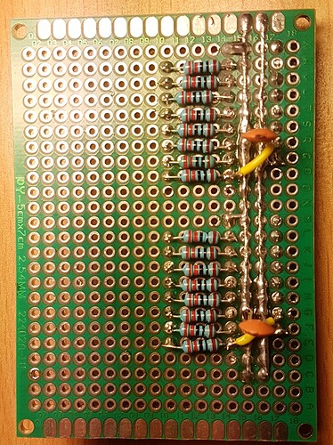
So far I only soldered this onto the board:

I tested with a LED for shorts, since I don't think my multimeter has a function for that. Everything that should connect is connected, but I also get a very weak light (not a "full" short, rather a "mini" short) for some pins that are close to the VCC line. I can't see them connecting anywhere though. I thought it might be the flux, but I couldn't completely remove it.
Any idea what typical rookie mistake I made and why it's not a "full" short?

Also, when longer not touching the board and then testing ground and VCC, I get a short flash in the LED, but after that they seem to be isolated. Does it have something to do with the capacitors?

Just_some_dude:
Also, when longer not touching the board and then testing ground and VCC, I get a short flash in the LED, but after that they seem to be isolated. Does it have something to do with the capacitors?

Assuming you have fitted capacitors of a microfarad or more - possibly with 0.1 µF caps - that will be the capacitors.

A multimeter is the thing for seeking shorts, on the 200 Ohms range. Digital multimeters test resistance using the 200 mV scale, so will not detect diodes, transistors or "parasitic" or protection diodes. To detect those, they have a "diode test" range that is 2 V instead.

Suspect you were detecting your fingers with the faint LED glow. :grinning:

Just_some_dude:
I tested with a LED for shorts, since I don't think my multimeter has a function for that. Everything that should connect is connected, but I also get a very weak light (not a "full" short, rather a "mini" short) for some pins that are close to the VCC line. I can't see them connecting anywhere though. I thought it might be the flux, but I couldn't completely remove it.
Any idea what typical rookie mistake I made and why it's not a "full" short?

If you are testing with the IC's mounted that is the reason. It might also be through your fingers if you are touching both ends and your fingers a bit damp.
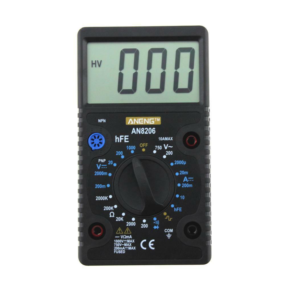
Most multimeters has continuity, I have reviewed many meters and also written some articles about them (See http://lygte-info.dk ).

Paul__B:
Assuming you have fitted capacitors of a microfarad or more - possibly with 0.1 µF caps - that will be the capacitors.

They are 0.068µF. I would understand that it appears when reversing polarity, but why do they charge up on their own?

Paul__B:
Suspect you were detecting your fingers with the faint LED glow. :grinning:

I was gonna say "How dare you assume I would actually be that stupid"....sadly I actually am, ouch :smiley:

HKJ-lygte:
Most multimeters has continuity, I have reviewed many meters and also written some articles about them (See http://lygte-info.dk ).

Unfortunately mine doesn't, maybe I should look into a new one.

Also I noticed another thing. In complete darkness there is a veeery weak light in the LED when connecting ground and VCC. The multimeter doesn't pick up any current on the 0.5mA scale though. Might that just be a very small leaking current from the capacitors?

Multimeters do not have a "continuity" scale - that makes no sense. It is however usual to have a piezo buzzer operative on the "diode test" scale that responds to a voltage less than the drop of a diode, thus indicating an actual low resistance connection.

Paul__B:
Multimeters do not have a "continuity" scale - that makes no sense. It is however usual to have a piezo buzzer operative on the "diode test" scale that responds to a voltage less than the drop of a diode, thus indicating an actual low resistance connection.

Sorry, maybe I should've been more precise on that. So the multimeter I got can measure DC mA, DC V, AC V and OHM x1k. No continuity testing. I still tested this with a LED, noticed a weak light when connecting ground and VCC, therefore I hooked the multimeter up to that circuit to measure how much current is leaking. I measured that on the 0.5mA scale of the multimeter and the indicator (analog multimeter) didn't move a bit. So I assume the current flowing is minimal.

My question would be if that might be a sign for some error in my soldering or if the capacitors are just leaking current.

Paul__B:
Multimeters do not have a "continuity" scale - that makes no sense. It is however usual to have a piezo buzzer operative on the "diode test" scale that responds to a voltage less than the drop of a diode, thus indicating an actual low resistance connection.

I have looked at over 100 different multimeters, they all have a "scale" in continuity mode, it show ohms, but the purpose of continuity is the fast reacting buzzer, that will sound when a low resistance is measured (Usual below 30-100ohm).
In diode test the meter shows volt and sometimes uses the buzzer.
A few cheap meter combines continuity and diode test, usually with a fairly bad result.

HKJ-lygte:
A few cheap meter combines continuity and diode test, usually with a fairly bad result.

More than "a few" actually! Most that do not auto-range.

Exception:

Different again!

Just_some_dude:
My question would be if that might be a sign for some error in my soldering or if the capacitors are just leaking current.

The capacitors will not be leaking current. If you put your fingers across them, that will leak current. And of course each time you swap the polarity applied to the capacitor it will draw current as it discharges and charges again.

Paul__B:
More than "a few" actually! Most that do not auto-range.

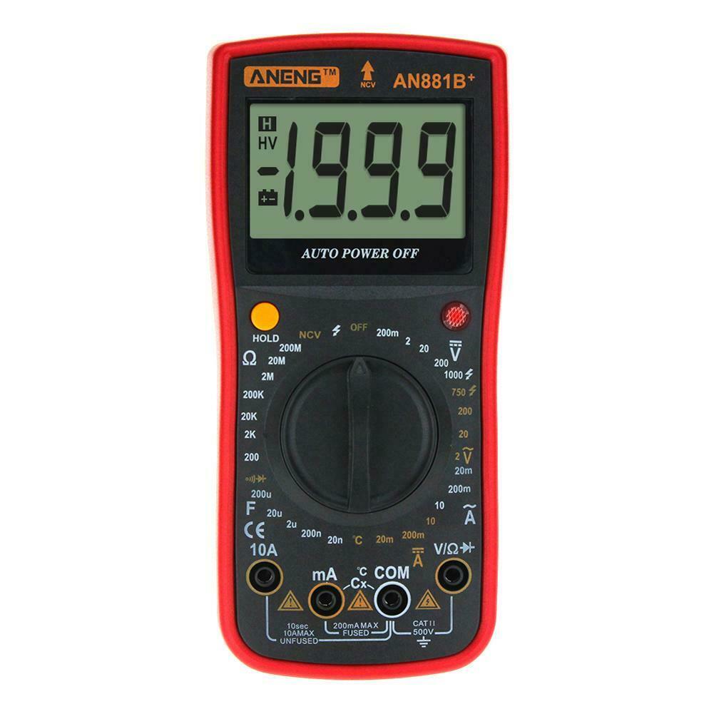
I believe that is correct, with manual range the positions on the rotary switch are needed for other ranges. The value shown on the display is usually neither volt or ohm (Aneng V7 is smarter).

Paul__B:
The capacitors will not be leaking current. If you put your fingers across them, that will leak current. And of course each time you swap the polarity applied to the capacitor it will draw current as it discharges and charges again.

Well in my case something is leaking when connecting ground and VCC with my LED, and not touching anything with my hands. Guess I need to redo the board completely to eliminate that error.

Hey guys :slight_smile:

I just wanted to give an update. I recently soldered the circuit onto a perfboard to check if the breadboard was causing any problems. I didn't solder the MOSFETs onto the perfboard yet, so that I could switch them out, to see if different ones make a difference.

When testing my perfboard, I noticed that the ghosting effect was just as present as with the breadboard. ::slight_smile:

But I finally got some different MOSFETs and tested them:

-The initial IRL540Ns still had the ghosting effect.
-New IRL540Ns (from a different seller) had the same result as the other FETs I tested (IRLR7843, IRLZ44N). They minimized the effect down to a point where I would say that it is acceptable and not really noticeable anymore. I could use this for my 8x8x8 project in the future. It is not perfect, but good enough.
-The BJTs I tested (BC337, 2N2222) still did the best job because the effect was the least visible when using them.