I might be wrong, but I have a dark brown suspicion it was the library used to control the segments that didn't work as expected. I followed 6v6gt's advise and erased all reference to the library. Subsequently I used his code (below) to control the segments, which did the trick!
OK. That is very good news. It looks great and the code is quite compact.
I'm curious about the decision to use AC (derived from the motor driver chip) for the filaments. For the long multi-digit tubes it is recommended to reduce the risk of a luminosity gradient across the digits. However, for a single digit tube I've not seen any discussion about it.
I'm just now designing a 6 digit IV-4 (16 segment + 2 dots) clock and am considering my options. The filaments are 50mA at around 2.5 volts so I will use a buck converter so it does not all get too warm. I'll be using HV5812 high voltage shift registers to drive them.
You could also (probably) have driven the L293D also from the Nano by re-arranging the pin assignment instead of a separate MCU chip.
You can tune the period (currently 5ms) that the tubes are lit for. To the human eye, 5ms is probably about right but if you start adding blank cycles to dim the tubes, that may introduce some noticeable flicker. In this case, a shorter cycle is preferred.
Oh and where is the antenna for the GPS module ? Is that on-board or do you use an external one? I live in a house of wood construction so I get good reception in-doors.
I'm curious about the decision to use AC (derived from the motor driver chip) for the filaments. For the long multi-digit tubes it is recommended to reduce the risk of a luminosity gradient across the digits. However, for a single digit tube I've not seen any discussion about it.
Good question. For quite some time I have had the filament of a single tube running on DC current. However a gradient was very well noticable. According to some articles I read on VFD tubes there would be some kind of risk of a buildup of some kind which could potentially lead to a shorter lifespan of the tube(s). Further investigation on low voltage AC drivers led me to hard to come by filament drivers. I wanted something that was more available and interchangeable. So I came to the decision to use a separate uC I had laying around (2313) and a H-bridge. I wrote a SPWM code for the 2313 and checked its output on the scope.
I'm just now designing a 6 digit IV-4 (16 segment + 2 dots) clock and am considering my options. The filaments are 50mA at around 2.5 volts so I will use a buck converter so it does not all get too warm. I'll be using HV5812 high voltage shift registers to drive them.
I just looked up the datasheet, very nice IC and not even that expensive too. To drive the filaments you might consider AC as well?
You could also (probably) have driven the L293D also from the Nano by re-arranging the pin assignment instead of a separate MCU chip.
Very true indeed, but I had one laying around and didn't want to go through the trouble of combining the SPWM code with the clock code.
You can tune the period (currently 5ms) that the tubes are lit for. To the human eye, 5ms is probably about right but if you start adding blank cycles to dim the tubes, that may introduce some noticeable flicker.
That's an interesting feature I will take into consideration. Any ideas on how to add blank cycles?
Oh and where is the antenna for the GPS module ? Is that on-board or do you use an external one? I live in a house of wood construction so I get good reception in-doors.
Currently the antenna is just a generic, active model (in the bottom-right of the picture) that comes with the Neo-6m module. I have ordered a smaller, active one with a longer connector wire which I aim to solder in a brass pole on the pcb. I think that will look the part.
Regarding the reception: similar situation here. For a (more or less) guaranteed reception I plan to place the clock near a window.
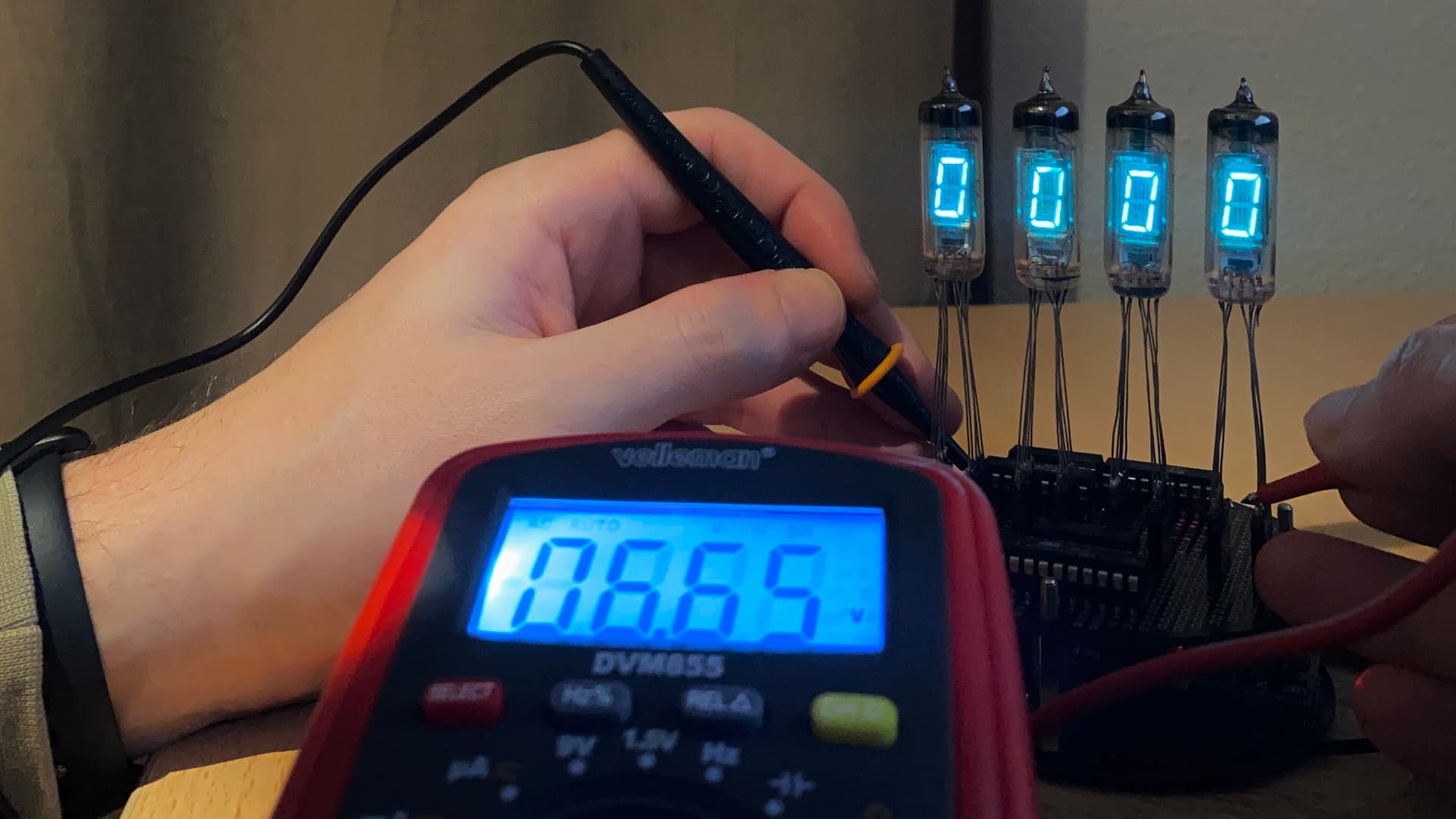
I ran into something equally interesting: I noticed the segments are slightly more dim than when individually powered with 27v. Not so strange as we are multiplexing all four of them. I now plan to increase to voltage for a brighter effect. As a reference for the calculation it would be safe to measure the grid pins.
Would it be correct to say that each grid pin has a high time of 5ms in a 20ms period? When I measure the grid pins it reads a duty cycle of 25%, 50Hz and almost 7v.
Duty Cycle = Pulse Width (sec) x Repetition Frequency (Hz) x 100
( (0.005sec x 50Hz) x 100) = 25
Also the 6.6volts on the grid sounds agreeable too, as 27v / 4 is in that range.
So if we have a duty cycle of 25%, an input voltage of 27v and an output of 6.6v it means my input has to by 4x greater. This means around 108v input. That doesn’t sound right to me...
According to a 'translation' of one of the IV-6 datasheet the anodes should be able to handle up to 70v 'in pulse'. The source driver on the other hand can only handle up to 50volts, but would it be safe to crank the supply voltage up to 50v?
I may have gotten way too mathematical with this, but I'm confused now and very eager to exchange some thoughts about this.
The following should implement display dimming. It works by interleaving cycles where no digit is displayed.
I'll look in detail at the heater calculations and comment later.
Clearly for your power calculations, there are some maximums to be observed. For example, I guess that in "pulse mode" a pulse has a maximum period (width) defined somewhere.
Be careful about calculations based on a digital voltmeter against PWM. The volt meter will integrate the results to give an average. However, the device under test may still be stressed by the over voltage. Example: 1000 volts with a 1% duty cycle may read as 10 volts. A 1% duty cycle could be 1 second on and 99 seconds off, or even longer, say in some heating applications.
// globals
. . .
volatile uint_t dimmerFactor = 0 ; // 0 is no dimming, 255 is the theoretical maximum
// for higher dimming factors, you may need to lower the
// period between calls of timerISR() to minimise visible flicker.
. . .
void loop() {
. . .
dimmerFactor = ??? ; // set this according to the ambient light. Experiment here
. . .
}
void timerISR()
{
// Every time this is called, it switches off the current tube, advances to the next tube,
// loads the segments for the next number to be displayed, then switches on the new tube to
// display it.
static uint8_t dimmerCycle = 0 ; // display active if dimmerCycle is 0
if ( dimmerCycle >= dimmerFactor ) dimmerCycle = 0 ;
else dimmerCycle++ ;
static uint8_t currentDigit = 0; // initialized once
for ( uint8_t i = 0 ; i < 4 ; i++ ) // switch off all the grids
digitalWrite( tube[ i ], LOW); // switch off all the grids
if ( dimmerCycle == 0 ) {
currentDigit++; // increment currentDigit
if (currentDigit == 4) currentDigit = 0; // wrap around so 0,1,2 and 3 are in a cycle
  digitalWrite( bcd_A ,  (displayVFD[currentDigit] & 0b00000001)  ? HIGH : LOW   ) ;
  digitalWrite( bcd_B ,  (displayVFD[currentDigit] & 0b00000010)  ? HIGH : LOW   ) ;
  digitalWrite( bcd_C ,  (displayVFD[currentDigit] & 0b00000100)  ? HIGH : LOW   ) ;
  digitalWrite( bcd_D ,  (displayVFD[currentDigit] & 0b00001000)  ? HIGH : LOW   ) ;
digitalWrite(tube [currentDigit], HIGH); // switch on grid for next tube
}
}
I'm sure you do need one but hurry because these are getting rare and expensive !
Incidentally, the IV-6 tubes are not real Nixies. They are, however, extremely attractive displays.
I actually have eight obsolete LM9022 VFD filament driver chips. I got these to use in an IV-18 project. I suppose then I had to buy a batch of 10 from the Ebay/Aliexpress retailer. https://datasheet.octopart.com/LM9022M/NOPB-National-Semiconductor-datasheet-11896945.pdf However, these are not ideal for the single tubes which have a lower voltage ( 2.6v ) filament and a relatively high current (50mA).
The datasheet example shows a constant duty cycle square wave circuit.
Your illustration implies a variable duty cycle square wave and I'm not sure what benefit that brings.
However, it has given me an idea of putting pairs of heaters in series, then each of the 3 pairs (6 tubes) in parallel. I could drive that assembly from 5 volts. However, then it almost enevitable that there would be a noticeable luminosity gradient across pairs of tubes because the anode to cathode voltage differential could vary, between the tubes, by up to 5 volts. I'd probably then have to use the L293 trick to even that out. I'd simply use a 50% duty cycle at a few kHz.
Good call that you bought eight of them, as they are getting harder to come by. I have been looking for them prior to the build, but was reluctant to buy them from China due to long shipping.
You are very correct about the variable duty cycle. I read a topic somewhere on the web that (VFD) tube filaments would benefit from a sine wave rather than a square wave. So this was my attempt at getting closest to a sine wave without having to use a transformer.
I can relate to your thoughts regarding putting the filaments in series, gave this some thoughts myself as well. But soon discovered that besides the luminosity gradient the property of tungsten is that its resistance changes non-linearly with temperature. This could lead to overvolting and probably constantly changing filament resistance. Maybe even shorter tube life? Then again, I am no tube expert, but it may be worth further investigating!
When choosing for the L293, a word of advice would be to please keep in mind to properly cool it as mine gets surprisingly warm (40+ish degrees).
Lastly I have a VFD clock update: I changed the 5ms interval to 2.5ms in order to see what this would mean for the brightness of the tubes. I am now measuring a slightly higher voltage (+/-16v) at the segment pins and as a bonus I dont see the 'flicker' of the GPS updating anymore. Happy days.