Hi,
I am planning on using uno to drive another device. The power source that triggers uno has 0V( as +) and -28V (as -). The plan is to use LM7805 to lower the source voltage to feed uno. I have connected -28V to the ground of LM7805 (and 0V to input of 7805 of course), assuming this connection will generate +5V to drive uno. Now is it fine to link the ground from uno to the ground on LM7805?? Or the ground from uno should be used for the circuit that only includes input to uno and output from uno??
Rochas:
Hi,
I am planning on using uno to drive another device. The power source that triggers uno has 0V( as +) and -28V (as -). The plan is to use LM7805 to lower the source voltage to feed uno. I have connected -28V to the ground of LM7805 (and 0V to input of 7805 of course), assuming this connection will generate +5V to drive uno. Now is it fine to link the ground from uno to the ground on LM7805?? Or the ground from uno should be used for the circuit that only includes input to uno and output from uno??
That is really not clear as described, I would want to see a schematic drawing to make sure. However it sounds like you have a real likelihood of applying a negative voltage (relative to common ground) to a positive voltage regulator, which will destroy it very quickly, if not also any loads attached to the output of the regulator including such as an arduino board. So try and supply a drawing if you want any kind of validation of what you wish to do, otherwise beware the magic smoke that lives inside electronic components, if it escapes the device the device will no longer function. ![]()
sorry that I didn't explain it clearly. Attached are the two circuits that I plan on using (sorry that I don't have software for this kind of drawing). Just not sure which grounding scheme is more appropriate. The first scheme treats the input to uno (reducing source power volt) and the output from uno as two circuits; the second one lumps them together. I worry that the 2nd one might accidentally feed undesired currently back to the power source (which will potentially blow the power source) if the relative voltage of uno ground is different from the ground of 7805. But I am not sure if scheme 1 is grounded sufficiently. Or maybe the basic design has some fundamental flaw?? Any suggestion will be greatly appreciated.


Rochas:
sorry that I didn't explain it clearly. Attached are the two circuits that I plan on using (sorry that I don't have software for this kind of drawing). Just not sure which grounding scheme is more appropriate. The first scheme treats the input to uno (reducing source power volt) and the output from uno as two circuits; the second one lumps them together. I worry that the 2nd one might accidentally feed undesired currently back to the power source (which will potentially blow the power source) if the relative voltage of uno ground is different from the ground of 7805. But I am not sure if scheme 1 is grounded sufficiently. Or maybe the basic design has some fundamental flaw?? Any suggestion will be greatly appreciated.
Well that is also confusing for different reasons. The polarity of you external power supply as wired to the 7805 appears to be ok, however you don't have the common side of the power supply (what you call -28) wired to a arduino ground pin, and that is required.
But also I don't understand why you have a jumper wire connecting what you call output (an output pin?) connected to a arduino ground pin? If that is the case if you ever set the output pin to a high (+5vdc) it would be a direct short to the arduino ground pin, which would destroy the output pin. So the wire you labeled with a ? is correct in the second drawing, but again both drawings show a jumper wire from arduino ground to something labled output, which is most certainly incorrect as stated before.
Lefty
have you considered isolation ?
either, use a dcdc converter to power the arduino,
or use isolated outputs of the arduino,
opto isolators might be what your after.
can you get parts easily ?
Thanks for the comments from both.
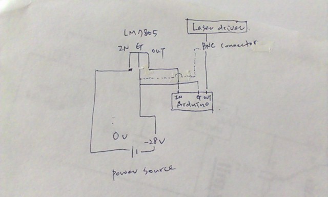
So the jump wire from uno output is actually to ground the metal part of female BNC connector (in the attached photo 2 yellow cable). Sorry maybe my drawing in that part isn't correct.
This is how I wire power source (white as 0v, red as -28V) to 7805, 7805 ouput pin to uno input pin, uno output pin to BNC (orange) and the ground from uno (blue).
So do you think grounding BNC in this setting will be an issue??
The access to part for me currently is radio shack. Am not very familiar with isolator, will that make the voltage conversion less cumbersome??


Well I'm reluctant to say it but your wiring maybe OK as best I can tell. ![]()
However you seem to lack input and output filtering capacitors for the 7805 voltage regulator. Check a datasheet for that regulator and you should be able to find the info for recommended cap sizes and try and locate them close to the regulator.
Good luck;
Lefty
Thanks Lefty. It's actually better if you wouldn't mind nit picking the wiring diagram (if it's not the ugly soldering...which I can't help much) for the potential problem.
I also made one with capacitors flank at both upstream of 7805 input and downstream of 7805 output. Is having capacitor going to make a big different on the stability of the circuit??
I tested both (with or without capacitors) with battery they seem work fine. But not very sure when they are hooked up to the real device that sends 28V. What you will do to use the power source I have (0V and -28V) in this case??
Is having capacitor going to make a big different on the stability of the circuit??
Yes a big effect.
I tested both (with or without capacitors) with battery they seem work fine.
How have you tested it, with a scope? Don't skimp on capacitors if you want a reliable circuit.
oh...I used jump wire to hook the (+) from a 12V battery to 7805 input, and the battery (-) to 7805 ground, and have BNC hooked up the the device that will be driven by uno. This setting seems to be fine with a very brief charge.
btw, what would be the potential harm by missing capacities?? I really have to think about it seriously, given the power source is very expensive. And do you think it's necessary to add another capacitor between 7805 ground and -28V??
ok...I really need help now. So I tested the entire setting (uno + the device that will be driven by uno) with 12v battery again and it worked fine (the program demands delivery of a 3s pulse twice and 3s LED blink twice). Next I powered the system with real external power source (0V and -28V) I planned to use. Without connecting the real device that uno is to drive, the power input to uno seems work well, as LED did blink according to the program. Then I hooked up the uno to the device, run the program again. This time uno run only once of the what the program demands, and then power source got shut down (we have a LED panel to read the output of power source), seems the circuit in the power source has been messed up. Any thought of what could be the potential problem here?? not having capacitors??
Rochas:
uno run only once of the what the program demands, and then power source got shut down (we have a LED panel to read the output of power source),
...
Any thought of what could be the potential problem here?? not having capacitors??
If the power source has stopped working then I think you need to consult people who know about that to find out why.
unlikely from what you say to be a capacitor problem, that is noramly an oscilation problem.
( A LDO is basically a high gain amplifier, so it oscillates great if you get the wrong output / input conditions )
sounds more like a blown uno or power supply.
The uno still works fine afterward when tested with battery or tested with 0v/-28v power source without downstream device being connected. Given the system can operate only once, it makes me feel the problem is coming from somewhere after uno is charged.
Is it likely that somehow the ground is sending some unwanted noise (from the output BNC connector due to the triggering of downstream device, please see photos in reply #5) back to the power power supply and that interferes with the circuit of power supply??
( A LDO is basically a high gain amplifier, so it oscillates great if you get the wrong output / input conditions )
Yes but an 7805 is not a LDO regulator.
unlikely from what you say to be a capacitor problem, that is noramly an oscilation problem.
That can cause things to shut down.
ok...I really need help now.
Yes and it is your own hands. Your description of what you are doing is less than clear. It is full of generalizations so it is difficult to spot any errors you have made.
Your schematics have been quite poor and do not show what you are wiring to what.
First thing to do is to find out why your power supply shut down. The normal reason is due to over current but it could be that you are feeding some voltage into the system or you power supply is not a floating one like you thought.
Is it likely that somehow the ground is sending some unwanted noise
No.
It does not help having a mystery 'downstream device' in the mix.
And do you think it's necessary to add another capacitor between 7805 ground and -28V??
Yes, the 7805 must have a capacitor on both input and output, it says so in the data sheet so do it. Only an idiot ignores what it says in the data sheet.
Hi Grumpy Mike, thanks for pointing out some potential problems I didn't think about before.
The basic idea is to use uno as an interface to drive a downstream device upon receiving an input from a external power source.
The power source itself is a device that delivers -28V to the power output. In it's own circuit, the 0V is used as common, which I suppose is the ground for the circuit within the device. In some of the modules (made by the same manufacture) that can be operated by the power supply, the (+) input to the module is connected to the 0+ wire of output ( and (-) of module to -28V wire). This feature makes me think that drawing positive voltage output from the power supply can be done by the same principle.
In the diagram (apologize that if it's not clear to you),the 0V wire is connected to the input of 7805, and -28V wire to the 7805 ground (and thanks for restating the need of capacitors). Output of 7805 to uno input pin, uno output pin to a BNC connector that will be hooked up to the downstream device. The uno ground is wired to 7805 ground. The metal part of BNC is also grounded to the same ground. Don't know if the attached diagram will be better (and apologize in advance if it's not).
Any other thought will be greatly appreciated!!
Hi
ok, so looks like you are trying to detect the -28 volts with the arduino.
have a look at an opto isolator,
such as these
http://www.skpang.co.uk/catalog/optoisolator-breakout-p-665.html
there are plenty of types,
the led is driven off your 28 volts, via a resistor , such that the current through the led is around 2 mA.
the output of the opto isolator is powered off the same as your arduino '5v' and 'gnd'.
the logic output of the opto isolator goes to an arduino input pin.
no common earth to worry about, cheap and very reliable.
Sorry but there are still lots of things that are not clear.
The power source itself is a device that delivers -28V to the power output.
OK but what is it. Is it a battery like you showed or is it some form of power supply derived from the mains. If it is then is the output voltage floating or is it tied to ground.
Output of 7805 to uno input pin,
Is this
a) An arduino input pin?
b) The +5V pin
c) The Vcc pin
d) The power input jack?
uno output pin
Is this
a) A signal output
b) the +5V pin
to a BNC connector that will be hooked up to the downstream device.
So how is this device powered? Is the ground of this tied to any other ground, a BNC plug implies it is. So that when you plug the BNC into your device you will be shorting out the arduino ground with mysterious downstream device.
Is the arduino connected to a computer through the USB at this point. This will act as another connection to the common ground.
It is my guess that this is what is going wrong, that the grounds are all not floating and therefore can't be connected together.
First, thanks for taking time helping.
OK but what is it. Is it a battery like you showed or is it some form of power supply derived from the mains. If it is then is the output voltage floating or is it tied to ground.
The power source is not a battery, and I have to apologize that the diagram given in this case is misleading. It's a power supply from a main module which delivers voltage output through its own circuit. I will assume the output voltage is likely not floating,
Output of 7805 to uno input pin,
Is this
a) An arduino input pin?
b) The +5V pin
c) The Vcc pin
d) The power input jack?
It's to one of the digital input pin on arduino
uno output pin
Is this
a) A signal output
b) the +5V pin
It is one of the digital output pin.
to a BNC connector that will be hooked up to the downstream device.
So how is this device powered? Is the ground of this tied to any other ground, a BNC plug implies it is. So that when you plug the BNC into your device you will be shorting out the arduino ground with mysterious downstream device.
This downstream device is actually a ADR laser driver, it is powered by an independent 110 VDC, and can take TTL modulation switch (which is what the BNC for). The driver should have its own ground.
Is the arduino connected to a computer through the USB at this point. This will act as another connection to the common ground.
The arduino is powered by a regular AC-DC adapter.
It is my guess that this is what is going wrong, that the grounds are all not floating and therefore can't be connected together
Thanks for pointing out this issue, I had a little concern initially about this grounding scheme, but since the arduino seems worked fine in the absence of downstream laser driver I didn't think too much about it.
I did another test today by removing the BNC from the ground and it didn't help either.
So in this case how will you ground the entire setting??
Again, much appreciated for any suggestion.
In that case I would go with the opto isolator suggestion in reply #16. There is no need to have a 7805 voltage regulator and it takes the -28V grounding out of the question.
First test that your Laser and arduino work together without the input voltage. If that works then use the -28V to drive the LED side of the opto through a sutiable resistor. Have the transistor side connected between the arduino input pin and ground and enable the internal pull up resistors.