Hi there!
I have just received my Arduino Mega 2560 kit with GSM Shield (with SIM5216E). I have connected both the kits and inserted the SIM card as well. During compilation itself I'm encountering errors but it was done. Then I tried to upload it the Arduino and I'm getting these error messages:
Arduino: 1.8.3 (Windows Store 1.8.6.0) (Windows 10), Board: "Arduino/Genuino Mega or Mega 2560, ATmega2560 (Mega 2560)"
In file included from C:\Program Files\WindowsApps\ArduinoLLC.ArduinoIDE_1.8.6.0_x64__mdqgnx93n4wtt\libraries\GSM\src/GSM.h:46:0,
from C:\Users\User\Documents\Arduino\sketch_jul03a\sketch_jul03a.ino:2:
C:\Program Files\WindowsApps\ArduinoLLC.ArduinoIDE_1.8.6.0_x64__mdqgnx93n4wtt\libraries\GSM\src/GSM3ShieldV1BandManagement.h:49:125: warning: 'typedef' was ignored in this declaration
Sketch uses 18254 bytes (7%) of program storage space. Maximum is 253952 bytes.
Global variables use 1110 bytes (13%) of dynamic memory, leaving 7082 bytes for local variables. Maximum is 8192 bytes.
avrdude: stk500v2_ReceiveMessage(): timeout
avrdude: stk500v2_ReceiveMessage(): timeout
avrdude: stk500v2_ReceiveMessage(): timeout
avrdude: stk500v2_ReceiveMessage(): timeout
avrdude: stk500v2_ReceiveMessage(): timeout
avrdude: stk500v2_ReceiveMessage(): timeout
avrdude: stk500v2_getsync(): timeout communicating with programmer
An error occurred while uploading the sketch
I don't have or the pin number for SIM card was disabled. Any help guys.
I have Arduino Mega running by itself. Done compilation and uploading but still Arduino can't receive SMS.
Does this have to do anything these warnings
In file included from C:\Program Files\WindowsApps\ArduinoLLC.ArduinoIDE_1.8.6.0_x64__mdqgnx93n4wtt\libraries\GSM\src/GSM.h:46:0,
from C:\Program Files\WindowsApps\ArduinoLLC.ArduinoIDE_1.8.6.0_x64__mdqgnx93n4wtt\libraries\GSM\examples\ReceiveSMS\ReceiveSMS.ino:21:
C:\Program Files\WindowsApps\ArduinoLLC.ArduinoIDE_1.8.6.0_x64__mdqgnx93n4wtt\libraries\GSM\src/GSM3ShieldV1BandManagement.h:49:125: warning: 'typedef' was ignored in this declaration
C:\Program Files\WindowsApps\ArduinoLLC.ArduinoIDE_1.8.6.0_x64__mdqgnx93n4wtt\libraries\GSM\examples\ReceiveSMS\ReceiveSMS.ino: In function 'void setup()':
C:\Program Files\WindowsApps\ArduinoLLC.ArduinoIDE_1.8.6.0_x64__mdqgnx93n4wtt\libraries\GSM\examples\ReceiveSMS\ReceiveSMS.ino:47:34: warning: deprecated conversion from string constant to 'char*' [-Wwrite-strings]
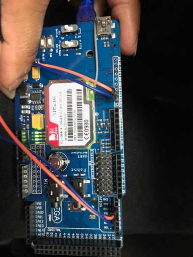
I'm getting session time out eorror when connecting the GSM mopdule directly onto the Arduino. As I have mentioned above I"m using ARDUINO 3G SHIELD SIM5216A and Arduino Mega 2560. Can anyone please confirm the pin connections as I have plugged the GSM module straight onto the Arduino pins shown in the below link.
Take a few steps backwards. Put a simple 'serial relay' program on the Arduino and see if you can get the modem to respond to basic AT commands - and make sure you are using ones that your chipset understands, although all should understand the basic codes.
I can't see a technical specification on the page you have linked to but I haven't looked very hard.
Yes, the first think is to get serial bus working into and out of the module. Then you should download at least AT commands list of the GSM chip/module which is used on the board. I can see it is from SIM com.
Two notes:
Web site mentions $150.00, is that Australian dollars dollars. I think it should cost less 50 US dollars or so.
To anyone, do not buy anything other than genuine Arduino GSM modems from Arduino shop. If you buy cheap GSM modem from elsewhere you get a lot of problems. What user Rishi sees now is just the beginning of problems.
thanks for your support guys. I have uploaded the code without connecting the shield. Compilation and Uploading done with warnings. Then I have connected the GSM shield and in serial monitor, all I can see is "SMS Messages Sender".
Can you please attach the code or point out where serial relay program is?
Also after uploading the program to Arduino and connecting the GSM shield I can see LED blinking turning the power switch ON. Does this mean GSM shield is responding to the program?
It appears you didn't follow the instructions offered above... at least not understanding what they suggested. You were a lot closer at post #1 than you are now.
So - now delete everything in the project folder, try the test examples suggestd above, and only then reconstruct the app from the original source and libraries as the project instructions say...
My guess is that you are jumping ahead of yourself with extra/duplicated libraries, missing files and other issues.
Your problems probably have nothing to do with the modem or wiring... that can be identified with the serial-relay ideas above ---
--- but are showing as a complete clusterf**k in the sketch installation & structure setup.
(Not the PC/Arduino application - that seems to be ok)
I have gone through all the replies above. Firstly, I have uploaded the ATCommandTest program and my serial monitor response was:
AT
AT
AT
AT
AT
DEBUG: GSM module is off
AT
AT
AT
AT
AT
DEBUG: GSM module is off
I have GSM fired up and can see 4-LED's out of which 1 is blinking. May I know why it's saying GSM Module is OFF?
Then, I have TestModem program uploaded. In Serial Monitor the response was:
Starting modem test...ERROR, no modem answer.
Checking IMEI...Modem's IMEI: 0
Resetting modem...Modem is functoning properly
Why does the modem failed to answer in starting test and saying that its functioning properly at the end? Programs I ran were attached below.
GSM Manufacture: https://www.itead.cc/itead-3g-shield.html
Any answers please?
As the message would suggest - the GSM module is off.
Is there a hardware pin used to power the module on / off ? Check.
Is your modem configured to interface at 57600 bps ? Check and confirm, or change the initialisation calls.
It seems the ATcommand... sketch is never getting past gsm.TurnOn()
(which is probably trying to send those multiple AT commands from within the library)
...hence never displays the version info, so anything beyond here is pointless.
The TestMode... sketch uses a different method of comms - but until you know more about your modem is just as likely to fail at the first hurdle.
Now go back to basics - as we have suggested several times.
// Quick & dirty full-duplex serial echo sketch
// to sort out modem connectivity issues.
// Uses two HARDWARE serial ports on a MEGA1280 / 2560 / 1284
// user can modify to use SoftwareSerial if needed
// or buy a real CPU with hardware ports!

void setup() {
 if (Serial.begin(115200)) // the serial monitor / console port
 Serial.print(F("\nThe console is open\n"));
 if (Serial1.begin(4800)) // the modem interface port
 Serial.print(F("\nThe modem port is open\n"));

 Serial.print(F("Serial-relay test\n\n"));
}

void loop() { // forever
 // echo console to modem
 if (Serial.available()) {
 char c = Serial.read();
 Serial1.write(c);
 }
 // echo modem to console
 if (Serial1.available()) {
 char c = Serial1.read();
 Serial.write(c);
 }
}
What hardware are you compiling for?
(Tools->Board menu)
As I mentioned in the previous post - this was written for MEGA 1280/2560/1284 based boards - you may need to tweak it for SoftwareSerial.
(I refuse to use SoftwareSerial - as it is intrinsically the wrong way to implement a serial port - that's just me.)
But the code will work fine - if you move Serial1 across to a SoftwareSerial port for your testing.
That will ONLY determine your wiring & modem are working.
You will still need to modify the other sketches sa needed to reflect the correct hardware/software connfiguration.
My hardware is Arduino Mega 2560 and I have selected the right board and port for compilation.To confirm my connection once again: I haven't connected my GSM module to external power supply other than Arduino Mega 2560 which is currently connected to the computer via. USB cable. And I have double checked the code you provided but not sure where I need to make changes? Sorry for the trouble but please help me with initial testing.
In the above mentioned website: I found this comment from Dave
"I have used this shield for a couple of weeks now, and if you are using it for 3G communications I would recommend using an Arduino Mega. I found that the Uno just didn't have enough memory once you started dealing with HTTP requests and responses and the increased software serial buffer sizes required. Another advantage of the Mega is that it has additional UART hardware serial pins, so you don't need to use the software serial library and can read and write to the shield at 115,200 bps.
If you use a mega, you can't use the jumpers on the shield to configure the serial pins as they don't correspond to the Mega's hardware UART pins and none of the mega pins you can use have the right interrupts available. You will need to remove the jumpers (or turn them 90 degrees so they don't do anything but you don't lose them) and patch the Tx and Rx pins from the shield to the hardware UART pins on the Mega (e.g. TX2 and RX2). Then in your sketch, it's just Serial2.begin(115200).
You also need to make sure you have sufficient power available to power the Arduino. A standard USB port is borderline and may cause inconsistent results so you are better off with an external power supply."
I hooked up GSM Module on top of Arduino and haven't used any external power supplies. Is it recommended to use them separately?
Also he mentioned about TxD and RxD pin connection, can you please tell me whether I have the connected it correclty?
OK - that's good news that you're using a MEGA2560 (I should have looked back - sorry)
Agree with the extra code space and RAM for larger applications.
The errors you are seeing in compilation have nothing to do with how the shield is connected - leave it off for now.
Let's just get the code to compile and upload before worrying about electricity.
Did you try my example sketch (in a new folder of it's own)? I had the same error using if(Serial.begin)) on a MEGA
Modified below... withotu the IF()
// Quick & dirty full-duplex serial echo sketch
// to sort out modem connectivity issues.
// Uses two HARDWARE serial ports on a MEGA1280 / 2560 / 1284
// user can modify to use SoftwareSerial if needed
// or buy a real CPU with hardware ports!

void setup() {
 Serial.begin(115200); // the serial monitor / console port
 Serial.print(F("\nThe console is open\n"));
 Serial1.begin(4800); // the modem interface port
 Serial.print(F("\nThe modem port is open\n"));

 Serial.print(F("Serial-relay test\n\n"));
}

void loop() { // forever
 // echo console to modem
 if (Serial.available()) {
 char c = Serial.read();
 Serial1.write(c);
 }
 // echo modem to console
 if (Serial1.available()) {
 char c = Serial1.read();
 Serial.write(c);
 }
}
So... This suggests the MEGA2560 core has HardwareSerial::begin() declared differently than the UNO etc... I hadn't noticed that before.
Give this code a shot - then modify you other code to remove the IF() conditions around Serial.begin()
Since I don't have your library, I'm not sure if you're performing all the initialisation steps.
In the instructions for your SMS library, do you have to ...
Wait for the > prompt (between remoteNum and txtMsg), or
Manually send CTRL-Z to terminate & send the message?
If either of these are missing, things won't work.
OP: Are you in Melbourne by any chance?
I've been using SIMCOM modems successfully with (a heavily modified version of) the FONA library for more than a year.
BTW, I took a look at your mode shield, and that header pin-link area - WILL allow you to assign MEGA ports 0-1-2-3 for the modem.
We'll get to that later, since it's working for now.