I'm completely new to Arduino and would love some guidance on a project I'm undertaking for my final year university project.
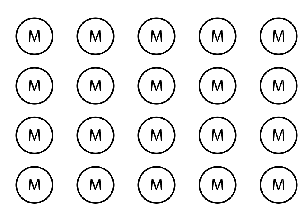
I'm looking to create an array of 20 vibrating disk motors (in a 4x5 grid with the possibility of adding another row) that can be activated individually and coded to create sequences/patterns.
These are the kind of motors that I'm hoping to use or similar:
Is anyone able to offer some guidance on what kind of board I'd need please? Along with anything else... I have access to an electronics lab at my university, so power supplies etc.
It seems the motors just need an ON or OFF signal so you just need an Arduino with enough I/O pins. A Mega should give you plenty of expansion room.
I note that the link says you can power the motors directly from an Arduino pin with a suitable resistor (make sure the current does not exceed about 20 mA) but even with that I would not try to power 20 of them from 20 pins.
Get the Arduino to operate a small transistor as a switch for each motor and give the motors their own power supply. The Pighixx website has examples of circuits for connecting to an Arduino.
Not a good idea to try to run all 20 motors at the same time when directly connected to output pins, even if properly current limited.
At 5V those motors take up to 100 mA. If you want to run them at full power you need drivers for each motor, or a high-current shift register such as the TPIC6B595 or the TPIC6A596. Those require just three Arduino pins (you can daisy chain them); 8 motors per shift register so you need three of them for your 20 motors. Much easier than building a dedicated transistor circuit for each of them.
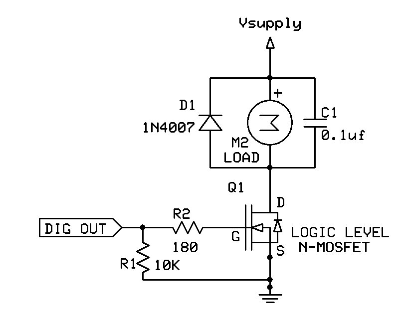
You will need a separate power supply, capable of supplying more than 2 Amperes, for the motors, as well as a driver for each one. A single NPN/MOSFET transistor + base/gate resistor will work. You also need a spike protection diode across each motor. See the diagram below, and don't forget to connect all the grounds.
Alternatively you could wire the motors in a 5x4 matrix and use fewer motor drivers, but some of them would have to be "high side" switches.
It will damage or reset the Arduino if you try to use the 5V output to power motors or servos.